
Design Guide


244
WALL HOODS
PLANNING INFORMATION
MODEL OPTIONS
When selecting a ventilation system, choose from one of our two
sophisticated appliance collections. Select Professional Series for the
ultimate in cooking and venting power or the Masterpiece
®
Series for
its sleek styling and numerous convenience functions. Thermador Wall
Hoods are available in various depths and heights to t your kitchen
plans and are meticulously crafted for both function and design. Be
sure to reference the correct model information in this design guide.
ELECTRICAL SPECIFICATIONS
Be sure your Thermador Wall Hood is properly installed and grounded
by a qualied technician. Installation, electrical connections and
grounding must comply with all applicable local codes.
Install a suitable conduit box (not furnished). An appropriately-
sized, UL-listed conduit connector must be used to correctly attach
the conduit to the junction box. Remote blowers require a 5-wire
installation.
INSTALLATION CONSIDERATIONS
The information in this design guide provides key features, product
dimensions, cutouts and installation specications. Before installing
a Thermador Wall Hood, be sure to verify the cutout dimensions
and electrical connections. Also, always consult with the installation
manual packed with the product for complete details before
installing.
INSTALLATION OPTIONS
Thermador Wall Hoods may be installed above a Thermador Range
or Cooktop to create a convenient cooking center. Refer to the
ventilation selection guide for compatibility.
Hood installation height above a range or cooktop can vary. To
obtain the necessary installation height above a Thermador Range or
Cooktop, consult the appliance’s installation manual. Accessory 6"
and / or 12" tall duct covers are used to ll the space between the
hood and ceiling.
Thermador Wall Hoods can be mounted on a wall or suspended from
a cabinet. The cabinet must be structurally joined to the wall studs to
support the weight of this hood.
MODEL REQUIRED CIRCUIT BREAKER
120V AC, 60 Hz
PH36GS 15; 20 A
PH42GS 15; 20 A
PH48GS 15; 20 A
PH54GS 15; 20 A
PH60GS 15; 20 A
PH30HS 15; 20 A
PH36HS 15; 20 A
PH48HS 15; 20 A
HPWB30FS 15 A
HPWB36FS 15 A
HPWB48FS 15 A
HMWN30FS 15 A
HMWN36FS 15 A
HMWN48FS 15 A
HMWB30FS 15 A
HMWB36FS 15 A
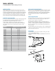
TRANSITIONS
– Included with PH__GS models (except 60") and PH__HS models
– 10" round downdraft transition
– Required for installation of 1000 and 1300 CFM inline and remote
blowers
– Included with PH60GS
9
5/
8
"
7
3/
8
"
88
3/3/
88
""
77
1/1/
44
""
88
3/3/
44
""
1313
11
//
88
""
77
11
//
22
""
5656
11
//
44
""
77
//
88
""
1212
66
11
//
44
""
1616
3/3/
44
""
2020
55
//
88
""