
Installation guide

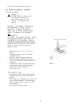

Wall
Mount
Installation
Note:
see
below
if
cabinet
installation
is
preferred
3.
After
the
hood
installation
height
has
been
determined
draw
a
horizontal
line
at
a
distance
above
the
cooktop
equal
to
the
desired
hood
installation
height
plus
7-
1/2”.
See
also
Figure
4a.
4,
Find
the
centerline
of
the
cooktop.
Draw
a
vertical
line
along
this
centerline
up
to
the
hori-
zontal
line
drawn
in
step
1
and
draw
a
vertical
line
right
and
left
at
a
distance
of
12-5/8”
to
determine
the
mounting
locationof
the
mounting
hooks
shipped
with
the
hood.
5.
Fit
two
mounting
hooks
on the
wall
to
hang
the
hood
through
the
provided
slots
(2
wall
anchors
+
2
hooks
+
2
screws
5x35).
6.
Run
10”
Duct,
long
enough
to
reach
the
transition
once
the
hood
has
been
installed
plus
1
1/2”
inch
to
connect
ductwork.
Fix
Duct
to
transition
with
screws
and
seal
withtape.
7.Remove
1
of
2
knockouts
and
install
1/2”
conduit
connector
in
j-box.
8.
Hang
the
hood
and
adjust
its
position
through
the
screws
on
the
hooks.
9,
Fix
the
hood
to
4
additional
point,
2
on
upperside,
2
on
lower
side
(use
4
wall
anchors
+
4washers
+
4
screws
5x35.
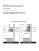
Cabinet
Installation:
Note:
See
above
if
wall
mount
installation
is
preferred
Note:
Distances
on
Table
3.3.
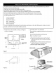
Find
the
centerline
of
the
cabinet
bottom.
Draw
a
line
along
this
centerline
from
rear
to
front
of
the
cabinet.
See
also
Figure
4b.
4.
Draw
two
lines,
one
at
a
K
distance
from
thewall,
the
other
one
at
a
Z
distance
from
theprevious
line.
Mark
4
points,
two
along
each
line
at
a
distance
of
half
W
from
the
center
line,
to
determine
the
screw
locations.
5.
Fit
4
screws
on
cabinet
bottom
do
not
tighten
completely
but
leave
a
space
of
about
1/2”
from
cabinet
bottom
surface
and
head
screws.
6.
Run
10”
Duct,
long
enough
to
reach
the
transition
once
the
hood
has
been
installed
plus1
1/2”
inch
for
connect
ductwork.
7.Remove
1
of
2
knockouts
and
install
1/2”conduit
connector
in
j-box.
8.
Hang
the
hood
on
screws
through
side
slots
provided
on
hood
top.Tighten
the
four
screws.
Note:
If
possible
fix
the
hood
on the
wall
at
4
additional
point
(2
on
upper
side,
2
on
lowerside).
9.
From
the
inside
of
the
cabinet
attach
the
transition
on
upper
outlet.
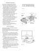
HOOD
WIDTH
|
DIM.
"W"|DIM.
"K"|
DIM.
"2"
30" 29
-
1/8"
|
2
-
1/2"
|
7
-
1/16"
36"
35
-
1/16"]
2
-
1/2"
|
7
-
1/16"
Table
3
i
Side
slot
x
4
Figure
4a
cat
Center
Hole
Knockouts
ASS
z
(junction
~
box)
.
—
Top
screw
location
Square
slot
bottom
fixing
screws
locations
Hook
for
wall
Screw
for
_
“installation
y
cabinet
a
bottom
-
25
3/16"
~
A
Pty
p*
Bs
installation
rao)
¥,12
5/8"
12
5/8"
*\adjusting
screw
Bottom
of
the
Hood
Figure
4b