
Operating Guide


20
switches or use any phone in the building. Shut off the valve on gas inlet line immediately and
contact gas supplier from a neighbor’s phone. Follow gas supplier’s instructions. If you can’t
reach the gas supplier, call the fire department. Only when you make sure there is no gas leakage,
go to the next step.
Note: During first seasonal use, gas smell is expected to be more noticeable than in standard operation.
Ignition Process:
1. Ensure that the two re-chargeable batteries have been placed in the heater as well as the normal
AA size batteries(1.5V) in the remote. Be sure to never insert the normal AA size batteries in
the heater or the rechargeable batteries in the remote.
2. At the battery slot on the heater, you will find an ON and OFF switch. Set it to ON.
3. Push down and release the SET button. At this point, the igniter should be clicking. The pilot and
the burner will come ON within 5-10 seconds.
4. If the pilot and burner do not come on within 15 seconds, the unit will automatically try to relight a
second time after 30 seconds.
Note: If the heater does not come ON after two attempts, hold in on the “SET” button for 5 seconds for
complete shutdown and repeat step 3 again.
5. After the heater’s burners have activated, you can set the remote control to your desired
temperature using the Up (˄) and Down (˅) arrows.
Shutdown Process:
To stop the heater, shut off the valve on the gas inlet line. Next, press the power button on the remote to
turn off the unit. If the unit will not be used again in a short period, switch the battery switch to the OFF
position, or remove the batteries when not using the unit for extended periods of time.
Note: Adjustable temperature settings determine the length of time that the heater will operate at
maximum BTU to achieve desired temperature, not the actual flame height.
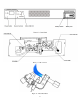
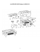
INSPECTING BURNER
Check pilot flame pattern and burner flame pattern often.
PILOT FLAME PATTERN
Two pilot burners with ODS function for NAT and LP gas respectively are installed on burners two sides
separately as shown in Figure. 11. The normal ODS pilot flame should have a correct pattern as shown in
Figure. 12 in normal operation with exception during ignition stage.