
User Manual


Theia lens motor controller instructions
Theia Technologies® motor control
v.180628
ESD protection is provided to these signals by Littelfuse®* SP724AHTG clamping diode arrays. Please see its
datasheet for details.
3.5. Reset (JP1)
Pin 5 of JP1 (see above) is an active-low reset input to the board. It has a pull-up resistor of 4.7 kOhm. ESD protection
is provided to it by a Littelfuse®* SP724AHTG clamping diode array. Please see its datasheet for details.
*/ Littelfuse is a trademark of Littelfuse Inc., USA
3.6. General Purpose I/O
Some Pins on some connectors could be reprogrammed into GPIO if certain interfaces are not needed. They could
then be used to drive certain periphery like LEDs or read input. Please ask if such special features are needed.
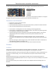
3.7. Lens Connectors (J23, J4, J5, J6)
These connectors are intended for cables coming from the lens. More details can be found in the lens datasheet.
J23 Zoom and Focus stepper motor coil connections
J4 P-iris stepper motor coil connections
J5 IR cut filter coil connections
J6 Zoom and Focus end point switches
Those functions work independently from each other. So for instance manual lenses with a P-iris may also be
interfaced.
The end point switches are optional. The board needs a software setting to work with them – and would fail to work
properly with that setting if the switches were missing.
3.7. Power Supply (J1, JP1, J2)
As mentioned above in the sections covering the connectors J1, JP1 and J2 there are several ways to supply power
to the board. It is important to note that all the power pins of those connectors are directly connected – all three
GND pins are connected and all three +5 Volt pins are connected (note that this includes USB).
DO NOT use more than one power supply at the same time because there are always small differences in their
voltages and high cross currents would most probably run through the board – leading to energy loss, heat and
may even end up in overheating and ignition.
The board is also not intended to be used for power distribution. It may be tempting to receive the power via USB
and then serve it to periphery connected to one of the connectors mentioned here. However we discourage to use
such a topology. The user would be responsible to check the current capability of the connectors and monitor the
heat of the PCB traces under worst case conditions in order to verify how much energy can be distributed safely that
way. He would also have to make the correct setting to the register telling the USB bus what the maximum power
requirement is – adding the stepper motor current of the lens to that going to the additional periphery (see below).
Depending on the device supplying energy to the USB bus that request may be denied if such a high current could
not be supplied. That would disable the stepper motor operation.
The common +5 Volt supply line goes through a Texas Instruments®* TPD3S014-Q1 which limits the supply current
to the board – both its maximum level and its rush-in rate on power-up. Please refer to the datasheet of that chip
for the details.
*/ Texas Instruments is a trademark of Texas Instruments Incorporated, Dallas, Texas, USA