
User Manual


Theia lens motor controller instructions
Theia Technologies® motor control
v.180628
3. Connectors
3.1. USB (J1)
Micro USB connector able to supply and control the board via a single cable. This connector interfaces with a FTDI®*
FT200 USB to I2C bridge chip and uses drivers available for that chip. That way this interface appears as a serial port
under some major operating systems. General compatibility is USB 2.0 but please refer to the datasheet of that chip
to get full information about its features and compatibility.
The I2C side of that bridge chip is also connected to the I2C lines accessible at connector J2. Configuration options
accessible through software need to be used to decide which interface (USB or I2C) to use. By default, the USB
interface is active.
The USB interface is protected by a Texas Instruments®** TPD3S014-Q1 which limits the supply current and provides
ESD protection. Please refer to the datasheet of that chip for the details. Additional protection and filtering comes
from passive elements, the FT200 and the controller chip.
*/ FTDI is a trademark of Future Technology Devices International Ltd, Glasgow, United Kingdom
**/ Texas Instruments is a trademark of Texas Instruments Incorporated, Dallas, Texas, USA
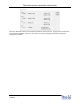
3.2. I2C (J2)
J2 is a Molex®* 53047-0610 or compatible connector. The fitting cable connector might be the Molex®*
51021-0600 or compatible.
J2 has a total of 6 circuits (pins) of which the I2C interface uses two for its signals. To function the board would
additionally need a ground reference (GND) and a 5V power supply. Both are available on J2 as well.
3 – I2C SCL
4 – I2C SDA
5 – Power GND
6 – Power +5 V
6
5
4
3
2
1
J 2