Thecus N8900 series/N12000 series/N16000 series N5550/N6850/N8850/N10850 N7700PRO V2/N7710 series N8800PRO V2 /N8810U series N4510U series/N7510 User’s Manual
Copyright and Trademark Notice Thecus and other names of Thecus products are registered trademarks of Thecus Technology Corp. Microsoft, Windows, and the Windows logo are registered trademarks of Microsoft Corporation. Apple, iTunes and Apple OS X are registered trademarks of Apple Computers, Inc. All other trademarks and brand names are the property of their respective owners. Specifications are subject to change without notice. Copyright © 2014 Thecus Technology Corporation. All rights reserved.
Safety Warnings For your safety, please read and follow the following safety warnings: Read this manual thoroughly before attempting to set up your Thecus IP storage. Your Thecus IP storage is a complicated electronic device. DO NOT attempt to repair it under any circumstances. In the case of malfunction, turn off the power immediately and have it repaired at a qualified service center. Contact your vendor for details.
Table of Contents Copyright and Trademark Notice ................................................... 2 About This Manual ......................................................................... 2 Limited Warranty........................................................................... 2 Safety Warnings ............................................................................ 3 Table of Contents .......................................................................... 4 Chapter 1: Introduction .......
SNMP Support .............................................................................. 68 UI Login Function ......................................................................... 69 System Network .................................................................................. 70 Networking .................................................................................. 70 DHCP/RADVD ............................................................................... 71 Linking Aggregation ..........
USB and eSATA Storage Expansion .................................................... 176 Remote Administration ...................................................................... 176 Part I - Setup a DynDNS Account ..................................................178 Part II - Enable DDNS on the Router ..............................................178 Part III - Setting up Virtual Servers (HTTPS) ...................................178 Firewall Software Configuration .....................................
Chapter 1: Introduction Overview Thank you for choosing the Thecus IP Storage Server. The Thecus IP storage is an easy-to-use storage server that allows a dedicated approach to storing and distributing data on a network. Data reliability is ensured with RAID features that provide data security and recovery—over multiple Terabyte of storage are available using RAID 5 and RAID 6.
Thecus IP storage supports multiple RAID volumes on one system. So, you can create RAID 0 for your non-critical data, and create RAID 1,5,6,50 or 60 (depend on model) for mission-critical data. Create the RAID levels depending on your needs. To configure RAID modes on the Thecus IP storage, refer to Chapter 4: Storage Management >RAID Information. iSCSI Capability Thecus IP storage is not only a file server, but it also supports iSCSI initiators.
Package Contents N8900/N12000/N16000 Series/N8800PRO V2/N8810U series/ N4510U-R/N4510U PRO-R The Thecus IP storage should contain the following common items: System Unit x1 QIG (Quick Installation Guide) x1 CD-Title (Acronis backup CD & Universal CD) Ethernet Cable x1 Accessory bag x1 HDD Compatibility list Card x1 Multiple Languages Warranty Card x1 Power cord x2 N6850/N8850/N10850/N7700PRO V2/N7710 series/N5550/N4510U-S/ N7510/N4510U PRO-S The Thecus IP storage should contain the following
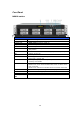
Front Panel N8900 series: Front Panel Item 1.Power Button • 2.Power LED • 3.System error LED • 4.Mute button • 5.USB Port • 6. Locator button / LED 7. RST 8. LAN 9. BUSY 10.OLED 11.Up Button ▲ 12.Down Button ▼ 13.Enter Button ↵ 14.Escape Button ESC • • • • • • • • • • • • Description Power on/off N8900 Solid green: System is power on. Solid RED: System error. Mute the system fan alarm. USB 2.
N12000 series: The Thecus N12000 series front panel has the device’s controls, indicators, and hard disk trays: Front Panel Item 1.Power Button • 2.Power LED • 3.System error LED • 4.Mute button • 5.USB Port • 6. Locator button / LED 7. RST 8. LAN 9. BUSY 10.OLED 11.Up Button ▲ 12.Down Button ▼ 13.Enter Button ↵ 14.Escape Button ESC • • • • • • • • • • • • Description Power on/off N12000 Solid green: System is power on. Solid RED: System error. Mute the system fan alarm. USB 2.
N16000 series: The Thecus N16000 series front panel has the device’s controls, indicators, and hard disk trays: Front Panel Item 1.Power Button • 2.Power LED • 3.System error LED • 4.Mute button • 5.USB Port • 6. Locator button / LED 7. RST 8. LAN 9. BUSY 10.OLED 11.Up Button ▲ 12.Down Button ▼ 13.Enter Button ↵ 14.Escape Button ESC • • • • • • • • • • • • Description Power on/off N16000 Solid green: System is power on. Solid RED: System error. Mute the system fan alarm. USB 2.
N6850: The Thecus N6850’s front panel has the device’s controls, indicators, and hard disk trays: 1. 2. 3. 4. 5. 6. 7. 8. 9. 10. 11. 12. 13. Front Panel Item Description Power Button • Power on/off N6850 USB Port • USB 2.0 port for compatible USB devices, such as digital cameras, USB disks, and USB printers. USB Port • USB 3.0 port for compatible USB devices, such as digital cameras, USB disks, and USB printers.
N8850: The Thecus N8850’s front panel has the device’s controls, indicators, and hard disk trays: Front Panel Item Description 1. Power Button • Power on/off N8850 2. USB Port • USB 2.0 port for compatible USB devices, such as digital cameras, USB disks, and USB printers. 3. USB Port • USB 3.0 port for compatible USB devices, such as digital cameras, USB disks, and USB printers. 4. LAN2 LED • Solid white: LAN2 Cable link • Blinking : Network activity 5.
N10850: The Thecus N10850’s front panel has the device’s controls, indicators, and hard disk trays: Front Panel Item Description 1. Power Button • Power on/off N10850 2. USB Port • USB 2.0 port for compatible USB devices, such as digital cameras, USB disks, and USB printers. 3. USB Port • USB 3.0 port for compatible USB devices, such as digital cameras, USB disks, and USB printers. 4. LAN2 LED • Solid white: LAN2 Cable link • Blinking : Network activity 5.
N7700PRO V2/N7710 series: The Thecus N7700PRO V2/N7710 series front panel has the device’s controls, indicators, and hard disk trays: Front Panel Item Description 1.Power LED • Solid blue: System is power on. 2.System LED • Solid orange: system is being upgraded or system startup; data currently inaccessible 3.WAN/LAN1 LED • Solid green: network link • Blinking green: network activity 4.LAN2 LED • Solid green: network link • Blinking green: network activity 5.
N8800PRO V2/N8810U series: The Thecus N8800PRO V2/N8810U series front panel has the device’s controls, indicators, and hard disk trays: Front Panel Item Description 1.Power Button • Power on/off N8800PRO V2/N8810U series 2.Power LED • Solid green: System is power on. 3.Reboot Button • Press to system reboot 4.System fan alarm • Solid red: system fan failure notification LED 5. Mute button • Mute the system fan alarm. 6.USB Port USB 2.0 port for compatible USB devices, such as USB disks, USB printers 7.
N5550: The Thecus N5550 front panel has the device’s controls, indicators, and hard disk trays: Front Panel Item 1.System LED 2.WAN/LAN1 LED 3.LAN2 LED 4.USB Copy LED 5.Syetem Warning LED 6.Reset Button 7.USB Port 8.Power Button/ Power LED 9.Up Button ▲ 10.Down Button ▼ 11.Enter Button ↵ 12.Escape Button ESC 13.LCD Display 14.
N4510U: The Thecus N4510U front panel has the device’s controls, indicators, and hard disk trays: Front Panel Item Description 1. LCD Display • Displays the current system status and warning messages. • Displays hostname, WAN/LAN1/LAN2 IP addresses, RAID status, and current time. 2. Up Button ▲ • Push to scroll up when using the LCD display. 3. Down Button • Push to scroll down when using the LCD display. ▼ 4.Enter Button ↵ 5. Escape Button ESC 6. Locator Button 7. USB Port 8. PWR LED 9.
N4510U PRO: The Thecus N4510U PRO front panel has the device’s controls, indicators, and hard disk trays: 1. Front Panel Item LCD Display 6. 7. Up Button ▲ Down Button ▼ Enter Button ↵ Escape Button ESC Locator Button USB Port 8. 9. PWR LED Busy LED 2. 3. 4. 5. Description • Displays the current system status and warning messages. • Displays hostname, WAN/LAN1 IP addresses, RAID status, and current time. • Push to scroll up when using the LCD display.
N7510: The Thecus N7510 front panel has the device’s controls, indicators, and hard disk trays: Front Panel Item Description 1.Power LED • Solid blue: System is power on. 2.System LED • Solid orange: system is being upgraded or system startup; data currently inaccessible 3.WAN/LAN1 LED • Solid green: network link • Blinking green: network activity 4.LAN2 LED • Solid green: network link • Blinking green: network activity 5.USB Copy LED • Solid blue: files are being copied from a USB storage device 6.
Rear Panel N8900 Back Panel Item 1.Power Connector • 2.Serial Port • 3.eSATA Port • 4.USB Port • 5.USB Port 6.WAN/LAN1 Port • • 7.LAN2 Port • 8.LAN3 Port • Description Connect the included power cords to these connectors This port is for external UPS device eSATA port for high-speed storage expansion USB 2.0 port for compatible USB devices, such as USB disks, and USB printers USB 3.0 port for compatible USB devices.
5.USB Port 6.WAN/LAN1 Port 7.LAN2 Port 8.LAN3 Port • USB 3.0 port for compatible USB devices. • WAN/LAN1 port for connecting to an Ethernet network through a switch or router • LAN2 port for connecting to an Ethernet network through a switch or router • LAN3 port for HA connecting. N12000V/N12000PRO: N12000V/N12000PRO rear panel features ports and connectors. Back Panel Item 1.Power Connector • 2.Serial Port • 3.eSATA Port • 4.USB Port • 5.USB Port 6.WAN/LAN1 Port • • 7.LAN2 Port • 8.LAN3 Port 9.
N16000: The N16000 rear panel features ports and connectors. Back Panel Item 1.Power Connector • 2.Serial Port • 3.eSATA Port • 4.USB Port • 5.USB Port 6.WAN/LAN1 Port • • 7.LAN2 Port • 8.LAN3 Port • Description Connect the included power cords to these connectors This port is for external UPS device eSATA port for high-speed storage expansion USB 2.0 port for compatible USB devices, such as USB disks, and USB printers USB 3.0 port for compatible USB devices.
N16000V/N16000PRO: N16000V/N16000PRO rear panel features ports and connectors. Back Panel Item 1.Power Connector • 2.Serial Port • 3.eSATA Port • 4.USB Port • 5.USB Port 6.WAN/LAN1 Port • • 7.LAN2 Port • 8.LAN3 Port 9.HDMI Port 10.Line in 11. Line out 12. Mic input • • • • • Description Connect the included power cords to these connectors This port is for external UPS device eSATA port for high-speed storage expansion USB 2.
N6850: The N6850 rear panel features ports and connectors. Back Panel Item 1.Power Connector • 2.Serial Port • 3.eSATA Port • 4.USB Port • 5.USB Port 6.WAN/LAN1 Port • • 7.LAN2 Port • 8.HDMI Port 9.Line in 10. Line out 11. Mic input 12. User GPIO • • • • Description Connect the included power cords to these connectors This port is for external UPS device eSATA port for high-speed storage expansion USB 2.0 port for compatible USB devices, such as USB disks, and USB printers USB 3.
N8850: The N8850 rear panel features ports and connectors. Back Panel Item 1.Power Connector • 2.Serial Port • 3.eSATA Port • 4.USB Port • 5.USB Port 6.WAN/LAN1 Port • • 7.LAN2 Port • 8.HDMI Port 9.Line in 10. Line out 11. Mic input 12. User GPIO • • • • Description Connect the included power cords to these connectors This port is for external UPS device eSATA port for high-speed storage expansion USB 2.0 port for compatible USB devices, such as USB disks, and USB printers USB 3.
N10850: The N10850 rear panel features ports and connectors. Back Panel Item 1.Power Connector • 2.Serial Port • 3.eSATA Port • 4.USB Port • 5.USB Port 6.WAN/LAN1 Port • • 7.LAN2 Port • 8.HDMI Port 9.Line in 10.Line out 11.Mic input 12. User GPIO • • • • Description Connect the included power cords to these connectors This port is for external UPS device eSATA port for high-speed storage expansion USB 2.0 port for compatible USB devices, such as USB disks, and USB printers USB 3.
N7700PRO V2: The N7700PRO V2 rear panel features ports and connectors. Back Panel Item Description 1.LAN2 Port • LAN2 port for connecting to a local Ethernet network through a switch or router. 2.WAN/LAN1 Port • WAN/LAN1 port for connecting to an Ethernet network through a switch or router. 3.Serial Port • This port is for an external UPS device. 4.eSATA Port • eSATA port for high-speed storage expansion. 5.USB Port • USB 2.0 port for compatible USB devices, such as USB disks, and USB printers. 6.
N7710 series: The N7710 series rear panel features ports and connectors. Back Panel Item Description 1.Power Connector • Connect the included power cords to these connectors 2. WAN/LAN1 Port • WAN/LAN1 port for connecting to an Ethernet network through a switch or router 3. LAN2 Port • LAN2 port for connecting to an Ethernet network through a switch or router 4.USB Port • USB 2.0 port for compatible USB devices, such as USB disks, and USB printers 5.USB Port • USB 3.
N8800PRO V2: The N8800PRO V2 rear panel features ports and connectors. Back Panel Item 1.Power Connector • 2.Power Switch • 3.eSATA Port • 4.USB Port • 5.Serial Port 6.WAN/LAN1 Port 7.LAN2 Port Description Connect the included power cords to these connectors Switch for power supply eSATA port for high-speed storage expansion USB 2.
N8810U series: The N8810U series rear panel features ports and connectors. Back Panel Item Description 1.Power Connector • Connect the included power cords to these connectors 2. WAN/LAN1 Port • WAN/LAN1 port for connecting to an Ethernet network through a switch or router 3. LAN2 Port • LAN2 port for connecting to an Ethernet network through a switch or router 4.USB Port • USB 2.0 port for compatible USB devices, such as USB disks, and USB printers 5.USB Port • USB 344.
N5550: The N5550 rear panel features ports and connectors. Back Panel Item Description 1.Power Connector • Connect the included power cords to these connectors 2. WAN/LAN1 Port • WAN/LAN1 port for connecting to an Ethernet network through a switch or router 3. LAN2 Port • LAN2 port for connecting to an Ethernet network through a switch or router 4.USB Port • USB 2.0 port for compatible USB devices, such as USB disks, and USB printers 5.USB Port • USB 2.0 port for compatible USB devices. 6.
N4510U-R: Back Panel Item Description 1.Power Connector • Connect the included power cords to these connectors 2. WAN/LAN1 Port • WAN/LAN1 port for connecting to an Ethernet network through a switch or router 3. LAN2 Port • LAN2 port for connecting to an Ethernet network through a switch or router 4.USB Port • USB 2.0 port for compatible USB devices, such as USB disks, and USB printers 5.USB Port • USB 2.0 port for compatible USB devices. 6.eSATA Port • eSATA port for high-speed storage expansion 7.
N4510U PRO-R: Back Panel Item Description 1.Power Connector • Connect the included power cords to these connectors 2. WAN/LAN1 Port • WAN/LAN1 port for connecting to an Ethernet network through a switch or router 3. LAN2 Port • LAN2 port for connecting to an Ethernet network through a switch or router 4.USB Port • USB 2.0 port for compatible USB devices, such as USB disks, and USB printers 5.USB Port • USB 2.0 port for compatible USB devices. 6.eSATA Port • eSATA port for high-speed storage expansion 7.
N7510: The N7510 rear panel features ports and connectors. Back Panel Item Description 1.Power Connector • Connect the included power cords to these connectors 2. WAN/LAN1 Port • WAN/LAN1 port for connecting to an Ethernet network through a switch or router 3. LAN2 Port • LAN2 port for connecting to an Ethernet network through a switch or router 4.USB Port • USB 2.0 port for compatible USB devices, such as USB disks, and USB printers 5.eSATA Port • eSATA port for high-speed storage expansion 6.
Chapter 2: Hardware Installation Overview Your Thecus IP storage is designed for easy installation. To help you get started, the following chapter will help you quickly get your Thecus IP storage up and running. Please read it carefully to prevent damaging your unit during installation. Before You Begin Before you begin, be sure to take the following precautions: 1. Read and understand the Safety Warnings outlined in the beginning of the manual. 2.
▲ N4510U/N4510U PRO ▲ N7510 WAN/LAN1 port WAN/LAN1 port 2. Connect the provided power cord into the universal power socket on the back panel. Plug the other end of the cord into a surge protector socket.
N5550 power socket N4510U/N4510U PRO power socket 3. Press the power button on the Front Panel to boot up the Thecus IP storage.
▲ N7700PRO V2/N7710 series/ N7510 ▲ N8800PRO V2/N8810U series power button ▲ N4510U power button ▲ N4510U PRO 40 power button power button
Chapter 3: First Time Setup Overview Once the hardware is installed, physically connected to your network, and powered on, you can configure the Thecus IP storage so that it is accessible to your network users. There are two ways to set up your Thecus IP storage: using the Thecus Setup Wizard or the LCD display. Follow the steps below for initial software setup. Thecus Setup Wizard The handy Thecus Setup Wizard makes configuring Thecus IP storage a snap.
6. Name your Thecus IP storage and configure the network IP address. If your switch or router is configured as a DHCP Server, configuring the Thecus IP storage to automatically obtain an IP address is recommended. You may also use a static IP address and enter the DNS Server address manually. 7. Change the default administrator password.
8. Finished! Access the Thecus IP storage Web Administrator Interface by pressing the Start Browser button. You can also configure another Thecus IP storage at this point by clicking the Setup Other Device button. Press Exit to exit the wizard. NOTE The Thecus Setup Wizard is designed for installation on systems running Windows XP/2000/vista/7 or Mac OSX or later.
Display Mode During normal operation, the LCD will be in Display Mode. Display Mode Item Host Name WAN/LAN1 LAN2 Link Aggregation System Fan1 System Fan2 CPU Fan 2009/05/22 12:00 Disk Info RAID Current Current Current Current Current Current Current Current Current Current Description host name of the system. WAN/LAN1 IP setting. LAN2 IP setting. Link Aggregation status system fan1 status. system fan2 status. CPU fan status system time. status of disk slot has been installed RAID status.
NOTE You can also change your LCD password using the Web Administration Interface by navigating to System Management > Administrator Password. For more on the Web Administration Interface, see Chapter 4: System Management. OLED Operation(Does not apply to the N7700PRO V2/N8800PRO V2/ N7710 series/N8810U series/N5550/N4510U series/N7510) OLED Operation The Thecus IP storage is equipped with an OLED on the front for easy status display and setup.
3. The LCD will display “USB Copy?” 4. Press Enter (↵) and the Thecus IP storage will start copying USB disks connected to the front USB port. The LCD will display the USB copy progress and results. Typical Setup Procedure From the Web Administration Interface, you can begin to setup your Thecus IP storage for use on your network. Setting up the Thecus IP storage typically follows the five steps outlined below.
To find out about configuring Folder Access Control Lists, see Chapter 4: Storage Management > Share Folder> Folder Access Control List (ACL). Step 5: Start Services Finally, you can start to setup the different services of Thecus IP storage for the users on your network.
Chapter 4: System Administration Overview The Thecus IP storage provides an easily accessible Web Administration Interface. With it, you can configure and monitor the Thecus IP storage anywhere on the network. Web Administration Interface Make sure your network is connected to the Internet. To access Thecus IP storage Web Administration Interface: 1. Type the Thecus IP storage IP address into your browser. (Default IP address is http://192.168.1.
Following the disclaimer page, you will see the Web Administration Interface. From here, you can configure and monitor virtually every aspect of the Thecus IP storage from anywhere on the network. My Favorite The user interface with “My Favorite” shortcut allows the user to designate often used items and have them display on the main screen area. The figure below displays system favorite functions.
Menu Bar The Menu Bar is where you will find all of the information screens and system settings of Thecus IP storage. The various settings are placed in the following groups on the menu bar: Menu Bar Item System Information System Management System Network Storage User and Group Authentication Network Service Application Server Module Management Backup Description Current system status of the Thecus IP storage. Various Thecus IP storage system settings and information.
Message Bar You can get quick information about your system status by moving your mouse over these icons. Message Bar Item Status Description RAID Information. Display the status of created RAID volume. Click to go to RAID information page as short cut. Disks Information. Display the status of disks installed in the system. Click to go to Disk information page as short cut. Display system FAN Status. Click to go to System Status page as short cut. FAN. Network.
System Information Information provides viewing on current Product info, System Status, Service Status and Logs. The menu bar allows you to see various aspects of the Thecus IP storage. From here, you can discover the status of the Thecus IP storage, and also other details. System Information Once you login, you will first see the basic system Information screen providing Manufacturer, Product No., Firmware Version, and System Up Time information.
System Fan 1 Speed System Fan 2 Speed System Fan 3 Speed System Fan 4 Speed CPU Temperature System Temperature System Temperature System Temperature System Temperature System Fan Speed Up Time Service Status Item AFP Status NFS Status SMB/CIFS Status FTP Status TFTP Status Rsync Status UPnP Status SNMP 1 2 3 4 Displays current System fan (left 1) status Displays current System fan (left 2) status Displays current System fan (left 3) status (Depend on model) Displays current System fan (left 4) status (De
Log Level ALL: Provides all log information including system, warning, and error messages. INFO: Shows information about system messages. WARN: Shows only warning messages. ERROR: Shows only error messages. Export Records Delete Records Auto Refresh The number of lines per page □ Sort Ascending Sort Descending |<< < > >>| Export all logs to an external file. Clear all log files. Specify the auto refresh time interval. Specify the desired number of lines to display per page.
User Access Log The User Access Log Support section allows administrators to select the desired protocols to record user activity for. User Access Log User Access Log Item Description User access log Enable or disable the User Access Log service. Folder Select from the dropdown list where to store the user access log. Service Select from the check box which access details to record. Apply Click Apply to save changes.
To export details from the User Access Log as a single file from target folder, administrators must first select the desired number of records from the dropdown list and also select the “Auto export” option. Please choose the number of logs export and click “Apply” to activate these settings.
Other than the defined items sent upon registration, there are also two additional items: “HDD Info” and “Time Zone”. These two optional items can also be sent to Thecus anonymously for analysis and statistics purposes. To send these items, simply check the desired checkboxes to help Thecus improve its products and services. Syslog Management Generates system log to be stored locally or remotely, it also can be chose to act as syslog server for all other devices.
Configuration with syslog client and target to store locally: Configuration with syslog client and target to store remotely: See the following table for a detailed description of each item: Time Item Syslog Daemon Syslog service Target Syslog folder Log Level Remote IP Address Description Enable/Disable syslog daemon.
System Monitor The system monitor is capable to monitor system status including CPU/memory utilization, fan/temperature status, network throughput and on-line user list in various protocols. To monitor system status, simply click on “System Monitor” from the tree menu and the screen will appear as below. It is divided into 4 sections. Each section can be modified to monitor specific items by using the drop down list from the “Monitors” tab, simply click on the items you would like to monitor.
For the on-line users list, system monitor will display the on-line users and the share folder they have visited. System Monitor Item Save Layout Reset Layout History Lock Layout Description Saving selected monitoring items. Layout will remain the same for future visits. Set back to default monitoring settings and layout. Click on this check box and system monitor will write the monitoring history to a designate path in the RAID volume. All of the monitoring items are fixed and cannot be changed.
System Management The System Management menu gives you a wealth of settings that you can use to configure your Thecus IP storage system administration and functions. You can set up system time, system notifications, and even upgrade firmware from this menu. Time: Setting system time From the time menu, choose the Time item and the Time screen appears. Set the desired Date, Time, and Time Zone. You can also elect to synchronize the system time on Thecus IP storage with an NTP (Network Time Protocol) Server.
Notification Configuration Item Description Beep Notification Enable or disable the system buzzer that beeps when a problem occurs. Email Notification Enable or disable email notifications of system problems. Authentication Type Select the SMTP Server account authentication type. SMTP Server Specifies the hostname/IP address of the SMTP server. Port Specifies the port to send outgoing notification emails. SMTP Account ID Set the SMTP Server Email account ID. Account Password Enter a new password.
WARNING Do not turns off the system during the firmware upgrade process. This will lead to a catastrophic result that may render the system inoperable. Schedule Power On/Off Using the Thecus IP storage System Management, you can save energy and money by scheduling the Thecus IP storage to turn itself on and off during certain times of the day. From the menu, choose the Schedule Power On/Off item and the Schedule Power On/Off screen appears.
Administrator Password From the menu, choose the Administrator Password item and the Change Administrator Password screen appears. Enter a new password in the New Password box and confirm your new password in the Confirm Password box. Press Apply to confirm password changes. There is also a password to enter the OLED setting that you can setup here. Enter a new password in the New Password box and confirm your new password in the Confirm Password box. Press Apply to confirm password changes.
Factory Default From the menu, choose the Factory Default item and the Reset to Factory Default screen appears. Press Apply to reset Thecus IP storage to factory default settings. WARNING Resetting to factory defaults will not erase the data stored in the hard disks, but WILL revert all the settings to the factory default values. Reboot & Shutdown From the menu, choose Reboot & Shutdown item, and the Shutdown/Reboot System screen appears.
Click Yes to reboot the system. Once the system has rebooted, you will be returned to the File System Check prompt. There you will see the available RAID volumes to run the file system check. Check the desired RAID volumes and click Next to proceed with the file system check. Click Reboot to reboot without running the check. Once you click Next, you will see the following screen: Click Start to begin the file system check. Click Reboot to reboot the system.
NOTE The system must be rebooted before Thecus IP storage can function normally after file system check completes. Wake-Up On LAN (WOL) The Thecus IP storage has the ability to be awoken from sleep mode via WAN/LAN1 or LAN2 port. From the menu, choose the WOL item, and the Wake-up On LAN screen appears. From here, you can Enable or Disable.
fields. With the SNMP management software, you can get other system’s basic information. From the menu, choose the SNMP item, and the SNMP Support screen appears. From here, you can Enable or Disable. UI Login Function Adjusts UI Login Configuration settings, you can enable/disable the Web Disk, Photo Server and modules functions, according to your needs.
System Network Use the System Network menu to make network configuration settings to an on board network port or additional NIC as well as DHCP and link aggregation. Networking From the System Network menu, choose Networking, and the Networking Configuration screen appears. This screen displays the network parameters of the global setting and available network connection. You may change any of these items and press Apply to confirm your settings.
Network Configuration (NIC port) Link speed Display associated NIC port link speed. Link status Display associated NIC port link status. MAC address MAC address of the network interface. Jumbo Frame Support Enable or disable Jumbo Frame Support of associate interface on your Thecus IP storage. IPv4/IPv6 Mode IP Click to enable IPv4/IPv6 for TCP/IP. The default is IPv4 enabled. It can choose a static IP or Dynamic IP. IP address of associate NIC interface.
DHCP/RADVD Server Configuration A DHCP/RADVD server can be configured to assign IP addresses (IPv4) or Prefix (IPv6) to devices connected to the associated NIC port. DHCP Configuration Item Description DHCP/RADVD Service Enable or disable the DHCP/RADVD service to automatically assign IP address to PCs connected to associate NIC interface. Start IP (IPv4) Specifies the lower IP address of the DHCP range. End IP in (IPv4) Specifies the highest IP address of the DHCP range.
The associated screen shot will appear after the “+” is clicked. Select from available network port then move over to selected box. Click “Link” to confirm the selection. The newly created tab will appear for more settings required to complete the link aggregation configuration. Link1 Configuration Status Specifies the network ports being used with the associated link aggregation. Click on to modify the selected network ports.
Jumbo Frame Support Enable or disable Jumbo Frame Support of the associated interface on your Thecus IP storage. Link Type IPv4/IPv6 Mode IP Select from drop down list for desired mode. Click to enable IPv4/IPv6 for TCP/IP. The default is IPv4 enabled. It has to be a static IP with the link aggregation being used. IP address of link aggregation. Netmask/Prefix Length Gateway Input netmask for IPv4 and Prefix length for IPv6.
Storage Management The Storage menu displays the status of storage devices installed in the Thecus IP storage. It includes storage configuration options such as RAID and disk settings, folder configuration, iSCSI and ISO Mount. Disks Information (Refer Chapter 7 for FW v2.03.01 and after) From the Storage menu, choose the Disk Information item and the Disk Information screen appears. From here, you can see various installed SATA/SAS hard disks.
Disk No. Capacity Model Link Firmware Status Bad Block scan Indicates disk location. Shows the SATA hard disk capacity. Displays the SATA hard disk model name. Displays the hard disk interface and link speed Shows the SATA hard disk firmware version. Indicates the status of the disk. Yes to start scan Bad Block. S.M.A.R.T. Information On the Disk Information screen, the status of each disk will be displayed in the Status column. Clicking on the OK or Warning link will display the S.M.A.R.
Test Type transfer it to the reserved disk area (spare area), and mark this sector as remapped. If this attribute value remains at zero, it indicates that the quality of the corresponding surface area is low. Set short or long time to test. Test Result Test Time Result of the test. Total time of the test. NOTE If the Reallocated Sector Count > 32 or Current Pending Sector of a hard disk drive > 0 , the status of the disk will show “Warning”.
RAID Information Item Description Master RAID The RAID volume currently designated as the Master RAID volume. ID ID of the current RAID volume. NOTE: All RAID IDs must be unique. RAID Level Shows the current RAID configuration. Status Indicates status of the RAID. Can read either Healthy, Degraded, or Damaged. Disks Used Hard disks used to form the current RAID volume. Total Capacity Total capacity of the current RAID. Data Capacity Indicates the used capacity and total capacity used by user data.
storage volume. To create a RAID volume, follow the steps below: 1. On the RAID Information screen, clicks create. 2. On the RAID Configuration screen, set the RAID storage space as JBOD, RAID 0, RAID 1, RAID 5, RAID 6, RAID 10, RAID 50 or RAID 60 (depends on model)— see Appendix B: RAID Basics for a detailed description of each. NOTE N8900/N12000/N16000 Series supports multiple RAID modes and are capable of creating up to five RAID volumes within a single NAS system. 3. Specify a RAID ID.
4. If this RAID volume is meant to be the Master RAID volume, tick the Master RAID checkbox. NOTE In a multiple RAID configuration, one RAID volume must be designated as the Master RAID volume. The Master RAID volume will store all installed modules. If the Master RAID is changed to another location (i.e. assigning volume 2 to be the Master RAID volume after volume 1 had been previously assigned), then all modules must be reinstalled.
We strongly recommended copying the RAID volume encryption key to a safe place. You can find the encryption key file from the USB disk in the following format: (RAID volume created date)_xxxxxx.key WARNING Please keep your USB disk in a safe place and also backup the encrypted key. There is no way to rescue data back if the key is lost. NOTE With RAID volume encryption enabled, the system performance will go down.
NOTE Single volume size supported: ext3 8TB XFS 48TB ext4 36TB 9. Press Submit to build the RAID storage volume. 10. Press “Yes” for RAID volume creation preparation. Then click “Finish” to start up with RAID volume building.
Building a RAID volume may be time consuming, depending on the size of NOTE hard drives and RAID mode. In general, if the RAID volume building process is up to “RAID Building”, then the data volume is accessible. WARNING Creating RAID destroys all data in the current RAID volume. The data will be unrecoverable. RAID Level You can set the storage volume as JBOD, RAID 0, RAID 1, RAID 5, RAID 6, RAID 10, RAID 50 or RAID 60 (depending on model).
Level JBOD RAID 0 RAID 1 RAID 5 RAID 6 RAID 10 RAID 50 RAID 60 WARNING Description The storage volume is a single HDD with no RAID support. JBOD requires a minimum of 1 disk. Provides data striping but no redundancy. Improves performance but not data safety. RAID 0 requires a minimum of 2 disks. Offers disk mirroring. Provides twice the read rate of a single disk, but same write rate. RAID 1 requires a minimum of 2 disks. Data striping and stripe error correction information provided.
Remove RAID Click to remove the RAID volume. All user data and iSCSI created in the selected RAID volume will be deleted. To remove a RAID volume, follow the steps below: 1. On the RAID List screen, select the RAID volume by clicking on its radio button, and click RAID Information to open the RAID Configuration screen. 2. On the RAID Configuration screen, click Remove RAID. 3. A confirmation screen will appear, you will have to click “Yes” to complete the “Remove RAID” operation.
WARNING Remove RAID destroys all data in the selected RAID volume. The data will be unrecoverable.
Global Hot Spare Up to 5 RAID volumes can be created per system. The global hot spare support can eliminate the redundant disk usage in each RAID volume. Simply select an unused disk from the global hot spare disk list then apply to activate. Expanding a RAID To expand a RAID 1, RAID 5, or RAID 6 volume, follow the steps below: 1. Replace one of the hard drives in the RAID volume and allow it to automatically rebuild. 2. Once rebuilt, you can continue to replace any remaining disks in the RAID array. 3.
Migrating a RAID Once a RAID volume has been created, you may want to move it to other physical drives or change the RAID array all together. To migrate a RAID 1, RAID 5, RAID 6, RAID50 or RAID 60 volume, follow the steps below: 1. From the RAID Configuration screen, click Migrate RAID. 2. A list of possible RAID migration configurations will be listed. Select the desired migration scheme and click Apply. 3. The system will begin migrating the RAID volume.
NOTE Migrating a RAID volume could take several hours to complete The RAID migration feature is available only when it is configurable. Here is a list of limitation with RAID level migration function: 1. During RAID level migration, it is not permitted to reboot or shutdown system. 2. For RAID migration from R1 to R5 or R1 to R6, all services will restart and “iSCSI” volume will be in read only mode but read/write of the “user data” will be possible during the operation.
Below is a table listing of possible RAID migration schemes: To From RAID 0 RAID 1 RAID 5 X RAID 5 RAID 6 [RAID 1] HDDx2 to [RAID 5] HDDx3 [RAID 1] HDDx2 to [RAID 5] HDDx4 [RAID 1] HDDx2 to [RAID 5] HDDx5 [RAID 1] HDDx2 to [RAID 5] HDDx6 [RAID 1] HDDx2 to [RAID 5] HDDx7 [RAID 1] HDDx2 to [RAID 5] HDDx8 ………………………………..HDDx16 [RAID 1] HDDx3 to [RAID 5] HDDx4 [RAID 1] HDDx3 to [RAID 5] HDDx5 [RAID 1] HDDx3 to [RAID 5] HDDx6 [RAID 1] HDDx3 to [RAID 5] HDDx7 [RAID 1] HDDx3 to [RAID 5] HDDx8 ………………………………..
RAID 6 X X [RAID 6] HDDx4 to [RAID 6] HDDx5 [RAID 6] HDDx4 to [RAID 6] HDDx6 [RAID 6] HDDx4 to [RAID 6] HDDx7 [RAID 6] HDDx4 to [RAID 6] HDDx8 ………………………………..HDDx16 [RAID 6] HDDx5 to [RAID 6] HDDx6 [RAID 6] HDDx5 to [RAID 6] HDDx7 [RAID 6] HDDx5 to [RAID 6] HDDx8 ………………………………..HDDx16 [RAID 6] HDDx6 to [RAID 6] HDDx7 [RAID 6] HDDx6 to [RAID 6] HDDx8 ………………………………..HDDx16 [RAID 6] HDDx7 to [RAID 6] HDDx8 ………………………………..
With the added stack target you can “Enable” or “Disable” the stack target now or later depending on usage required. Next, input the target IP address of the stackable device and click the Discovery button. The system will list available target volumes from the inputted IP address. Once the volume IP has been set, you may need to input a valid user name and password to validate your access rights. If there is no user name and password needed to access target volume, then leave it blank.
The Stacked Target name will become the network share name and will be displayed through network access such as SMB. You may refer to the figure below to see the result. Please note the naming limitation. From the figure above, the Stacked Target name is “pmmeeting”. The figures below show the result before and after via Microsoft Network Access when settings have been completed.
The Browseable setting is the same method used for setting a system share folder. It designates whether or not this folder will be visible through web disk. You may refer to the figure below for reference when Yes and No are selected. The Public setting will be set the same way as the setting for the system share folder associated with the ACL permission is. If Public is set to Yes, all users will be able to access it, and ACL button will be grayed out.
With this newly attached stack target device, you will see the information displayed and also have access to several options to choose from. In general, if the attached stack target device has been used by another Thecus NAS as stack target volume, then the Format item will be display and system will recognize it straight away and display its capacity. Otherwise, the Format item will be available and the Capacity and Status items will show as “N/A” and “Unknown file system” respectively.
After your changes have been made, click Apply to confirm any modifications. Once changes are applied, the associated information will be updated on the Stack Target List window. D. Stack Target ACL If the stack target Public setting set to Yes, then the ACL button will be grayed out. However, if Public setting is set to No, then the ACL button will be available for you to setup user access permissions for the stack target.
ISO Mount The ISO Mount feature is a very useful tool from the Thecus products. With it, users can mount an ISO file and have the export name display all the details from the mounted ISO file. From the main menu, the ISO Mount feature is located under “Storage”. Please refer the figure below for reference. Select the ISO Image Mounting function and the ISO Image Mounting window will appear as shown here. A. Add an ISO file From the figure above, select an ISO file from the drop down share list.
To mount the new ISO file, select one file from the list of files and input the desired mounting name into the “Mount as:” field. Click “ADD” to confirm the completion of the mounting. If nothing is input in the “Mount as” ISO file export name field, the system will automatically give an export name to the ISO file. The mounting name will then be defined by the ISO file name.
After completion, the page will display all mounted ISO files. You can click “Unmount” to eliminate a mounted ISO file. B. Using ISO The mounted ISO file will be located in the share folder of the same name as the file. Please refer the screen shot below. Here, the ISO file “Thecus 01” wasn’t assigned a mounting name, so the system automatically created a folder “Thecus 01”.
Share Folder From the Storage menu, choose Share Folders, and the Shared Folder screen appears. This screen allows you to create and configure folders on the Thecus IP storage volume. Adding Folders On the Folder screen, press the Add button and the Add Folder screen appears. This screen allows you to add a folder. After entering the information, press Apply to create new folder.
NOTE Folder names are limited to 60 characters. Systems running Windows 98 or earlier may not support file names longer than 15 characters. Modify Folders On the Folder screen, press the Edit button and the Modify Folder screen appears. This screen allows you to change folder information. After entering the information, press Apply to save your changes. Modify Folder Item RAID ID Folder Name Description Browseable Public Description RAID volume where the folder will reside. Enter the name of the folder.
NFS Share To allow NFS access to the share folder, enable the NFS Service, and then set up hosts with access rights by clicking Add. NFS Share Item Hostname Privilege OS Support ID Mapping Description Enter the name or IP address of the host Host has either read only or writeable access to the folder. There are two selections available: • Unix / Linux System • AIX (Allow source port > 1024) Choose the one which best fits your needs.
share (root:root). Guest system root account will be mapped to anonymous user (nobody:nogroup) on NAS. • All user on guest system will be mapped to anonymous user (nobody:nogroup) on NAS. Choose the one which best fits your needs. Choose to determine the data “Sync” at once or “Async” in arranged batch. Click to save your changes. • Sync / Async Apply Folder and sub-folders Access Control List (ACL) On the Folder screen, press the ACL button, and the ACL setting screen appears.
Writable Provides Write access to users or groups who are displayed in this column. Enable to inherit the access right for all its sub-folders. Recursive To configure folder access, follow the steps below: 1. On the ACL screen, all network groups and users are listed in the left hand column. Select a group or user from this list. 2. With the group or user selected, press one of the buttons from the three access level columns at the top.
2. From the drop down select the group you would like to search for the user in. 3. Click Search. NOTE The system will list up to 1,000 users from the chosen category. To narrow your search, enter a search term in the blank provided. Snapshot SMB and enterprise Thecus IP storage systems are now capable of saving 16 Snapshot versions of files and folders. For Snapshot to function, a “BTRFS” file system is required.
Taking a Snapshot Click on the “Snapshot” button. The management screen will then appear as below for the associated folder. To manually take a Snapshot, simply click “Take Snapshot” and the Snapshot history will be listed. It can store up to 16 versions. To locate where the Snapshot files or folders are stored, please browse to \\System_IP\Snapshot. Please note that you will need to have the relevant folder permissions enabled for your account.
and select the desired Snapshot interval. Options include Daily, Weekly, or Monthly. Since files and folders are limited to 16 Snapshots versions, the “Automatically remove oldest Snapshot” option allows for the removal of the oldest version automatically once the limit is reached. Snapshot Restore To restore a Snapshot, simply select the desired version from list and click “Restore”. Once the restore confirmation has been made, the selected Snapshot will overwrite the current associated file or folder.
NOTE To access the Snapshot folder, a user requires the relevant authentication rights. NOTE If the Snapshot folder is used for iSCSI purposes, it can only be restored from the WebUI (i.e. through the Snapshot feature) and cannot be done manually. Snapshot Removal To remove a Snapshot, simply select the desired version from list and click “Remove”.
iSCSI You may specify the space allocated for iSCSI. See the table below to the allowed iSCSI target number per system: Model N8900V N6850 N5550 N4510U series N7510 Allowed iSCSI volume 15 N8800PRO N12000V N16000V N7700PRO V2 N8800PRO V2 N7710 series N8810U series N10850 N8850 25 N8900 N12000 N16000 50 iSCSI Target To add iSCSI target volume, click iSCSI with associated RAID volume from its drop down list and select the desired RAID volume.
Advanced There are 3 options (iSCSI CRC/Checksum, Max Connections, Error Recovery Level) These currently allow the Admin to Enable/Disable the Thecus IP storage associated with the iSCSI setting. Delete Click this to delete the iSCSI Target. Allocating Space for iSCSI Volume To allocate space for an iSCSI target on the current RAID volume, follow the steps below: 1. Under the iSCSI Target List, select iSCSI Target then click Add. The Create iSCSI Volume screen appears.
Create iSCSI Volume Item Description iSCSI Target Volume Enable or Disable the iSCSI Target Volume. Target Name Name of the iSCSI Target. This name will be used by the Stackable NAS function to identify this export share. iqn_Year Select the current year from the dropdown. Iqn_Month Select the current month from the dropdown. Authentication You may choose CHAP authentication or choose None. Username Enter a username. Password Enter a password.
LUN ID iSCSI Block size Specific Logic unit ID number. The iSCSI block size can be set under system advance option, default is 512 Bytes. [ 4K ] block size while more than 2TB capacity will be configured in Windows XP. [ 512 Bytes ] block size for application like VMware etc. NOTE Be sure the iSCSI target volume has been enabled or it will not list out while using Initiator to get associated iSCSI target volumes. NOTE The iSCSI target volume creation will associate at least one LUN together.
2. Modify your settings. Press ok to change. Expand Volume The iSCSI volume is now able to expand its capacity from unused space (Instant Allocation mode only).
You will then see the dialog box displayed below. Drag the Expand Capacity bar to the size you want. Then press Expand to confirm the operation. Delete Volume To delete volume on the current RAID volume, follow the steps below: 1. Under the Volume Allocation List, click Delete. The Space Allocation screen appears.
2. Press YES. All data in the volume will be removed. iSCSI Thin-Provisioning If iSCSI Thin-Provisioning is selected when creating an iSCSI target volume, virtual memory is assigned to the target, allowing the physical memory to reach maximum capacity and adding new disks only when needed. To setup iSCSI thin-provisioning, simply select “Thin-Provision” mode from the “Create LUN” setting screen. Next, allocate capacity for the iSCSI thin-provision volume by dragging the Allocation bar to the desired size.
If creating an iSCSI target volume under “Instant Allocation”, physical memory is assign to the target, being limited by the available memory. For the iSCSI target volume created under “thin-provisioning”, virtual memory is assigned to the volume, which can go up to 16384GB (16TB). Advance Option There are 3 available options for the user to operate Thecus IP storage associated with iSCSI setting. The details are listed in the following screenshot.
To enable this option, the initiator can connect with “Data digest” and “Header digest”. Max Connections The maximum number of iSCSI connections. Error Recovery Level The Error Recovery Level (ERL) is negotiated during a leading iSCSI connection login in traditional iSCSI (RFC 3720) and iSER (RFC 5046). ERL=0: Session Recovery ERL=0 (Session Recovery) is triggered when failures within a command, within a connection, and/or within TCP occur.
WARNING Please be notified that if the system has been used as a standalone station before and contained more than one RAID volume with data inside, once it is used for HA, all of data will be destroyed. Let’s see an example with two Thecus Units. 1st unit: Host name: PMA (172.16.66.25) with JBOD RAID volume. This unit will be setup as the Primary server. 2nd unit: Host name: PMS (172.16.66.24) with JBOD RAID volume. This unit will be setup as the Secondary server.
WARNING The HDD capacity of HA Secondary server must be equal or greater than the Primary server or a warning message will appear. Setting up the Primary unit for HA. Let’s use the Primary unit from our example PMA (172.16.66.25): i. Login in to web UI of system 172.16.66.25. Then go to “High Availability” HA configuration page under the Storage category. ii. Click on “Enable” radio button, then the setting page will appear. iii.
iv. Choose the “Auto Failback” option, the default is disabled. For more details about auto failback, please refer to the description below. Auto Fail Back: In legacy Heartbeat clusters, the auto failback option would determine whether a resource would automatically fail back to its "Active" node, or remain on whatever node is serving it until that node fails, or an administrator intervenes.
1. Please select the network interface from the drop down list of physical connective available. It can be either on board LAN ports or additional add-in NIC, even 10G. 2. Input “Indicate” IP address. This “indicate IP” is used for the system to ping out then check whether the system is still alive. So please input an IP address that is going to response properly. 3. Filled in IP information for the “Virtual IP” and “Secondary Server IP” in either IPv4 or IPv6.
ix. Advance options can be setup by pressing the associated button. Heart Beats Configuration Item Description Keep alive time The keep alive directive sets the interval between heartbeat packets. It is specified according to the Heartbeat time syntax. Dead time The dead ping directive is used to specify how quickly Heartbeat should decide that a ping node in a cluster is dead. Setting this value too low will cause the system to falsely declare the ping node dead.
Setting up the Secondary unit for HA. The secondary unit for our example is PMS (172.16.66.24): xi. Login in to the web UI of the system 172.16.66.24 then go to “High Availability” HA configuration page under the Storage category. xii. Click on the “Enable” radio button, the setting page will appear. xiii. Choose the server role of the system, for this example, we will have this unit set as the “Secondary Server”. So “Secondary Server” is checked.
After the Secondary server has communicated with Primary Server successfully, then the state will changed to: Click “Yes” to reboot both Primary and Secondary server. If the communication has failed then you will see an error message as below. Conditions in which the secondary server will take over to play the role as Active: 1. Primary server RAID is damaged 2. Loss of the primary server’s data port connection 3.
At this time, the virtual IP address will be mapped to the PMS system because it is in an active state. HA Ready: After both Primary and Secondary systems has rebooted, the HA link status and the HA RAID volume can be seen from the HA status page. Please note, it will take 1~2 minutes to complete the primary and secondary servers’ role played. If both servers are displayed as standby, please wait for the systems to synchronize with each other. From the HA Primary server “PMA (172.16.66.
HA Recovery: If one of the HA member is down and need to be recovered, simply go to the RAID management page and the “HA Recovery” icon will be available. Click on the “HA Recovery” icon, then the system will prompt a box to inquire about the Active server heartbeat link IP address. After inputting the IP address and pressing Apply, the unit will be recovered fully.
If the other HA member is running smoothly, please choose “Recovery HA” to complete HA recovery. Or select “No, continue” to let both HA members has they are. WARNING WARNING If there are transfers in progress when the Primary server encounters problems and the Secondary server becomes active, the session will be stopped. Please contact your network administrator to determine whether or not your transfers were completed.
Item Work Group / Domain Name ADS Support ADS Server Name ADS Realm Administrator ID Administrator Password Apply Description Specifies the SMB/CIFS Work Group / ADS Domain Name (e.g. MYGROUP). Select Disable to disable authentication through Windows Active Directory Server. Specifies the ADS server name (e.g. adservername). Specifies the ADS realm (e.g. example.com). Enter the administrators ID of Windows Active Directory, which is required for Thecus IP storage to join domain.
Local User Configuration From the Accounts menu, choose the User item, and the Local User Configuration screen appears. This screen allows you to Add, Edit, and Remove local users. Local User Configuration Item Description Add Press the Add button to add a user to the list of local users. Edit Press the Edit button to modify a local user. Remove Press the Remove button to delete a selected user from the system. Add Users 1.
NOTE All users are automatically assigned to the ‘users’ group. Edit Users 1. Select an existing user from the Local User Configuration screen. 2. Click on the Edit button, and the Local User Setting screen appears. 3. From here, you can enter a new password and re-enter to confirm, or use the << or >> buttons to have this user join or leave a group. Click the Apply button to save your changes. Remove Users 1. Select an existing user from the Local User Configuration screen. 2.
Local Group Configuration From the Accounts menu, choose the Group item, and the Local Group Configuration screen appears. This screen allows you to Add, Edit, and Remove local groups. Local Group Configuration Item Description Add Press the Add button to add a user to the list of local groups. Edit Press the Edit button to modify a selected group from the system. Remove Press the Remove button to delete a selected group from the system. Add Groups 1.
5. Select users to be in this group from the Users List by adding them to the Members List using the << button. 6. Click the Apply button to save your changes. Edit Groups 1. On the Local Group Configuration screen, select a group name from the list. 2. Press the Edit button to modify the members in a group. 3. To add a user into a group, select the user from the Users List, and press the << button to move the user into the Members List. 4.
Batch Users and Groups Creation The Thecus IP storage can also add users and groups in batch mode. This enables you to conveniently add numerous users and groups automatically by importing a simple comma-separated plain text (*.txt) file. From the Accounts menu, click Batch Input and the Batch User and Group Cration dialogue will appear. To import your list of users and groups, follow these steps: 1. Click the Browse icon to locate your comma-separated text file.
User Quota The Thecus IP storage support local or AD users with storage quota limitations in each RAID volume of the system. To enable this function, simply click “Enable”, then apply. Next, each user can be setup a global storage quota size for each RAID volume. Simply click on “Quota Size” for each user and input the desired capacity. After the setup is complete, please click on “Apply” to activate the user quota size.
LDAP Support The LDAP is the other way to authenticate login users who has joined LDAP server, fill in the LDAP server information and get LDAP authentication started. Please make sure that the LDAP server has a Samba sam and a POSIX ObjectClass account. A description of each item follows: LDAP Support Item LDAP Service LDAP Server IP Base Domain Manager Password Apply Check ObjectClass Description Enable or Disable LDAP service. Input LDAP server IP address. Input base domain information ex.
Samba Service Used for letting the operating system of UNIX series and SMB/CIFS of Microsoft Windows operating system (Server Message Block / Common Internet File System).Do the link in network protocol. Enable or Disable SMB/CIFS protocol for Windows, Apple, Unix drive mapping. NOTE • In some environments, due to security concerns, you may wish to disable SMB/CIFS as a precaution against computer viruses. File Access Cache File Access Cache is default Enable.
UNIX Extension The default is enable for Samba usage, with situation using Mac OSX with smb connection may have permission issue. When it happened, please setup “UNIX Extension” disable to get issue solved. Samba Recycle Bin The Thecus IP storage is supported recycle bin via SMB/CIFS protocol. Simply enable the “Recycle Bin” function and “Recycle Folder Display” then all of deleted files/folders will reside in the “_NAS_Recycle_(Associated RDID Volume)” share folder.
There are 2 more setting could help to manage the recycle bin for deleted folders/files. 1. Setup the “Day” to remove deleted folders/files which has resided in recycle bin permanently. Left default value “0” if desired to clean up recycle bin manually. 2. Setup the “Size” for recycle bin to allow deleted folders/files can store. Left default value “0” with no limitation. NOTE • The deleted files/folders which have resided in recycle bin will keep its permission.
Time Machine Time Machine backup folder asterisk (*) to use the default setting. Click the enable checked box if you would like your MAC system to use the Thecus IP storage as MAC time machine backup. Select from the drop down list to designate the folder for time machine backup destination. NFS Setup From the System Network menu, choose the NFS item, and the NFS Support screen appears.
Security FTP Port External IP Passive Port Range (30000-32000) FTP ENCODE Allow Anonymous FTP Access Auto Rename Upload Bandwidth Download Bandwidth Enable or disable Security FTP, be sure the client FTP software has also security FTP setting enabled. Specifies the port number of an incoming connection on a non-standard port. Input the public IP address of the router when the Thecus secure FTP server has been enabled. This can help to respond to the ftp client with proper communication information.
Item TFTP IP Port Share Folder Folder Permission Description Enables TFTP Service on the Thecus IP storage. Checked WAN/LAN1 or LAN2 to enable port use Specifies the port number of an incoming connection on a non-standard port. Select the file stored folder, it cannot be empty. Select the folder permission WebService From the Network Service menu, choose the WebService item, and the WebService Support screen appears. This screen displays the service support parameters of the system.
Bonjour Setting Bonjour, is Apple Inc.'s trade name for its implementation of Zeroconf, a service discovery protocol. Bonjour locates devices such as printers, as well as other computers, and the services that those devices offer on a local network using multicast Domain Name System service records. This definitive guide walks you through Bonjour zero-configuration networking with a complete description of the protocols and technologies used to create Bonjour enabled applications and devices.
Item SSH Service Port SFTP Apply Description Enable or disable SSH service. The port number is default 22. Enable or disable SFTP protocol under SSH service. Click “Apply” to confirm the changes. DDNS To set up a server on the Internet and enable the users to connect to it easily, a fixed and easy-to remember host name is often required. However, if the ISP provides only dynamic IP address, the IP address of the server will change from time to time and is difficult to recall.
UPnP Port Management One of the most convent way to allow users to access required services such as FTP, SSH, web disk and http etc. from Internet environment is setting UPnP port management. To set up this UPnP port forwarding feature, please be sure that the router has “UPnP Service” Enabled. The following is an example from one of the router manufacture with UPnP Configuration page.
And click “Add Rule” to add more port mapping from Internet to access desired services or press “Refresh” to get most updated list. A description for each item as following: UPnP Port Management Item Description Start port Specific port number starts with. End port Specific port number ended Protocol Choose the protocol for port forwarding needed. Description Specific the port services if applicable. Apply Click “Apply” to confirm the changes.
iTunes® Server With the built-in iTunes server capability, Thecus IP storage enables digital music to be shared and played anywhere on the network! From the Network menu, choose the iTunes item, and the iTunes Configuration screen appears. You may enable or disable the iTunes Service from here. Once enabled, enter the proper information for each field and press Apply to save your changes.
Auto Module Installation Choose the Auto Module Installation item and the available system Module screen appears. The default for this module list is located online. So if the Thecus IP storage is capable to connect to Internet, then it will automatically link to the Thecus official website and list the available modules. Please refer the screen shot below. Another way to have auto module installed is to use the universal CD shipped with system. It contains a file “modules.
Auto Module Source List Item Description Installed Status of module Name Module name Version The version of the released module Description The description of the module Location The module is either located on-line or disk Document The available documentation of the module Action To install or delete module. p.s.
Rsync Target Server When it comes to backing up your data, it’s very important to have flexibility. Data guard provides you with many options, including full backup for all shares, custom backup for selected shares and iSCSI volume backup. Being based on the Linux operating system, it is also much more stable and experiences much less frequent data loss during transfer than other remote backup systems.
1. Enable Rsync Target Server 2. Add a username and password (they can be different than your NAS’s username and password) 3. Select Apply NOTE • You will need this user name and password while the data is going to remotely backup to this Rsync target server. Now Rsync is turned on your NAS, which means it can be used as a target for Rsync backup, in other words, only the backup NAS needs to be activated in this way.
Restore Log Restore NAS Configuration re-start the real-time operation. Restore the associated task Click to view the associated task in process details. Click to restore system configuration from selected destination to source unit. More details will describe in sections.
Custom Backup iSCSI Backup destination. It could also create shares automatically from destination if it is not existent. This only applies if the target server is the same model as the source. The “Custom backup” allows user to choose desired shares backup to destination. The “iSCSI backup” can backup iSCSI volume as single file to destination. Full Backup Click on full backup and the setup screen appear as below.
-Fill out all the necessary details and choose your parameters Add Rsync Backup Task Item Description Task Name Backup Type Sync Type Compress Backup NAS Config Resume Partial File Handle Sparse File Keep ACL Setting Log Location This is how this task will appear in the task list. Real time: It will backup folders/files from source to target on the fly. On the other hand, any changes from the source will back up to the target right away. Schedule: The task will start only according to the schedule.
Speed Limit Timeout Limit Enable Schedule Input the bandwidth control for data backup operation. Setup the timeout when trying to build up a connection in between the source and the target system. If backup is set as “Schedule”, please input the related period and time. After the required fields are filled and the parameters are setup, click ‘Finish” to complete. The data guard task will appear in the list as shown below. From the task list, you can now see the newly added task “fullback01”.
3. Click “Next” and more setting appears. These are the as the settings for “Full backup” 4. Click “Finish” and the data guard task will appear in the list as shown below. From the task list, you can now see the newly added “customback01”. This backup is setup as “schedule”.
iSCSI Backup If the source unit contains iSCSI volume, it can be backed up to the target unit as a single file. The procedure is the same as for the previous “Full backup” and “Custom backup”, select “iSCSI backup” from data guard wizard. 1. Inputs the share folder name of the target sever where the source is going to backup. The sub-folder can be left as blank. 2. Select the iSCSI target volume which you wish to back up to the target server. 3. Click “Next” and more settings will appear.
4. Click “Finish” and the data guard task will appear in the list as shown below. From the task list, you can now see the newly added “iscsiback”. This backup is setup as “schedule”. NOTE • The source folder name will use iSCSI_+target volume name. So here it is displayed as “iSCSI_pmtest”. pmtest is the iSCSI target name when the iSCSI target was created. The iSCSI backup can see the result as below. The task “iSCSI_pmtest” has backup to target 172.16.66.
NOTE • To restore task with backup type set as “Real time”, first you need to stop the task then you can proceed with the restore operation. Restore NAS Configuration This is a useful feature if the system configuration needs to be restored to a brand new unit. Let’s go thru the following example to see how it works. The original source system has 3 RAID volume, “RAID”, ‘RAID10” and “RAID20”, and has backed up the system configurations to the target server.
2. Click on “Restore NAS Configuration” and the screen shown below will appear. Input the target server’s IP address where the system configuration has been backed up, and necessary authentication info. Confirm by doing a “Connection Test” to make sure the communication between the source and the target server works. 3. Click “Next” and a screen will appear as shown below. It has the listed available system configuration backup files. Select the one you want and click next.
4. After clicking “Next”, a screen will appear as shown below. Listed on the left hand side, you will see the configuration backup details which contain the 3 RAID volumes. On the right hand side, you will see a list of single “RAID” volume. You may roll back to previous page to recall the example we have taken. 5. The backup configuration has different numbers of RAID volume than the current system (3 vs 1). It can be kept as the RAID volume mapping arranged by the system, then carry on to click “Finish”.
The current system has 2 RAID volumes, “RAID” and “RAIDa”. Select the RAID volume from the backup configuration volume list which is going to be mapped to the RAID volume of the current system. Simply click on the right hand side of “RAIDa” and a drop down list will appear. Now you can choose which volume to map with. In this case the “RAID01” volume from the system backup configuration will be mapped to the volume “RAIDa” of the current unit.
After inputting the ACL backup file and clicking the “Next” button, the system will show another screen to list the matched folders in between the backup file and this RAID volume. Just select the desired folders for the ACL restore. NOTE • The ACL backup will only back to share folder level; it does not apply to its sub-layer. • The ACL backup/restore can be used among ext3/ext4/XFS file system. ZFS can only be used with other RAID volume with ZFS file system created.
1. Write Files/folders to disc a. Click the Add button and the NAS share list appears. b. Select files/folders which you would like to burn. All of the selected folders/files will be seen under the disc label name “New Disc”. The disc label name can be changed by clicking on it and press “Edit” from menu bar. The selected folders/files also can be removed by clicking on them and then pressing “remove” or “remove all” for all selected items. c.
d. Select the burning speed from the drop down list. e. Select whether disc data verification is required or not. f. Click “Burn” to start disc burning. 2. Write image file to disc a. Click “Browser” and the NAS share list will appear to locate the desired image file to burn. b. Select the ISO file. c. Select from the installed USB or SATA(for N6850/N8850/N10850) burning devices. Please click the “detect disc” button to check the status once the disc is inserted. d.
3. Create image file from files/folders a. Click the Add button and the NAS share list will appear. b. Select the files/folders which you would like to burn. All of the selected folders/files will appear under the disc label name “New Disc”. The disc label name can be changed by clicking on it and pressing “Edit” from the menu bar. The selected folders/files also can be removed by clicking on them and pressing “remove” or “remove all” for all the selected items. c.
Disable USB Copy Simply select “Disable” for the USB Copy Service option and the USB Copy button or LCM/OLED USB Copy item will become inactive. Using USB Copy Enable the USB Copy service and select one of the 3 options available: “USB to NAS”, “NAS to USB”, and “Copy all USB files to NAS”. If select “USB to NAS” or “NAS to NAS”, you will also need to set up the type of backup desired.
Click on “Add” and select “Source Path” and “Target Path” from the drop-down list.
If you select “Copy all USB files to NAS”, then please choose the target path from the drop-down list. All files and folders on the USB device will be copied over to the NAS. NOTE If “Sync” mode has been selected, the target-side redundant folders/files will be deleted after a comparison has been conducted of the source. NOTE Once the USB Copy service has completed, the USB device will un-mount from system. To start another task, please re-insert the USB device.
Thecus Backup Utility The Thecus Backup Utility is on your Installation CD. When you click on the CD, the Backup Utility will be installed under Program Groups > Thecus > Thecus Backup Utility. If it is not installed, you can copy the file (Thecus Backup Utility.exe) to a convenient location on your hard disk and double click to execute it. NOTE If you can not find Thecus Backup Utility on your CD, please download it from the Thecus website (http://www.thecus.com).
2. When the Welcome to Microsoft Windows XP screen appears, click Perform Additional Tasks. 3. Click Browse this CD. 4. In Windows Explorer, navigate to ValueAdd > Msft > Ntbackup. 5. Double-click Ntbackup.msi to install the backup utility. Once installed, you can use the Windows Backup Utility by following the steps below: 1. Click Start, and point to All Programs > Accessories > System Tools > Backup to start the wizard. 2. Click Next to skip past the opening page.
Printer Information Item Description Manufacturer Displays the name of the USB printer manufacturer. Model Displays the model of the USB printer. Status Displays the status of the USB printer. Remove document Click to remove all documents from printer queue from Queue Restart Printer service Click to restart printer service If a corrupt print job is sent to a printer, printing may suddenly fail.
9. Click Finish. NOTE • Note that if a multi-function (all-in-one) printer is attached to the Thecus IP Storage, usually only the printing and fax functions will work. Other features, such as scanning, will probably not function. Windows Vista To set up the Printer Server in Windows Vista, follow the steps below: 1. Open Printer Folder from the Control Panel. 2. Click the right mouse button in anywhere on the Printers folder and then select Add Printer. 3.
4. Select The printer that I want isn’t listed. You can press The printer that I want isn’t listed to go into next page without waiting for Searching for available printers to finish. 5. Click Select a shared printer by name. Type http://:631/printers/usb-printer in the box, where is the IP address of Thecus IP storage. Click Next. 6. Select or install a printer and then press OK.
7. Windows will attempt to connect to the printer. 8. You can choose to set this printer as the default printer by checking the Set as the default printer box. Click Next to continue. 9. Done! Click Finish.
Uninterrupted Power Source From the External Devices menu, choose the Uninterrupted Power Source item and the UPS Setting screen appears. Make any changes you wish, and press Apply to confirm changes.
See the following table for a detailed description of each item. UPS Setting Item UPS Monitoring Remote UPS Monitoring Remote UPS IP Manufacturer Model Battery Status Power Seconds between power failure and first notification Seconds between subsequent power failure notifications Shutdown the system when the battery charge is less than Apply Description Enable or disable UPS monitoring. Enable or disable Remote UPS monitoring.
Part I - Setup a DynDNS Account 1. Go to http://www.dyndns.org from your home PC. 2. Click on the Sign Up Now link. 3. Check the Check boxes, select a user name (i.e.: N12000), enter your email address (i.e.: xxx@example.com), check Enable Wildcard, and create a password (i.e.: xxxx). 4. Wait for an email from www.dyndns.org. 5. Open the email and click on the link to activate your account Part II - Enable DDNS on the Router 1.
Replacing Damaged Hard Drives If you are using RAID 1, RAID 5, RAID 6, RAID 50 or RAID 60 you can easily replace a damaged hard drive in the Thecus IP storage while keeping your data secure with the system’s automatic data recovery. Hard Drive Damage When a hard drive is damaged and data in the RAID volume is corrupted, the system OLED will display a warning message and the system will beep. Replacing a Hard Drive To replace a hard disk drive in the Thecus IP storage: 1.
Chapter 6: Troubleshooting Forgot My Network IP Address If you forget your network IP address and have no physical access to the system, you can find out the IP address by either looking directly onto the Thecus IP storage OLED panel, or by using the setup wizard to retrieve the IP of your Thecus IP storage. 1. Start the Setup Wizard, and it will automatically detect all Thecus IP storage products on your network. 2.
Problems with Time and Date Settings The administrator is able to select an NTP Server to keep Thecus IP storage time synchronized. However, if Thecus IP storage cannot access the Internet, you may encounter a problem when setting the Time and Time Zone. If this happens: 1. Login to the Web Administration Interface. 2. Navigate to System Management>Time. 3. Under NTP Server, select No. 4. Set the Date, Time, and Time Zone. 5. Click Apply.
Chapter 7: Updates for FW v2.03.01 Changes for FW v2.03.
Added Hardware Information From the System Information category, choose the Hardware Information item and the system will display the related HW details for the associated model. Below is an example of the information for a Thecus N8900. Disk Information From the Storage menu, choose the Disk Information item and the Disk Information screen appears. From here, you can see various installed hard disks. The disk slot position will appear if the mouse is moved over the installed disk.
Disks Information Item Description Disk No. Indicates disk location. Capacity Shows the SATA hard disk capacity. Model Displays the SATA hard disk model name. Firmware Shows the SATA hard disk firmware version. Bad Block scan Yes to start scan Bad Block. S.M.A.R.T. Information On the Disk Information screen, select a disk then click on “Smart” to list the S.M.A.R.T. info of the associated disk. You may also perform a disk SMART test (doesn’t apply to SAS HDD); simply click “Test” to start the SMART test.
Test Type and transfers data to a special reserved area (spare area). This process is also known as remapping and "reallocated" sectors are called remaps. This is why, on a modern hard disks, you cannot see "bad blocks" while testing the surface - all bad blocks are hidden in reallocated sectors. However, the more sectors that are reallocated, the more a decrease (up to 10% or more) can be noticed in disk read/write speeds. Current count of unstable sectors (waiting for remapping).
The JBOD device will have a unique ID that ranges from 1 to 10. The disk no. lead ID will indicate the different JBOD devices. The screen shot below show a JBOD device with ID 4, so J4-6 is indicated under the JBOD device disk list with 6 slots. Data Guard (Local Backup) The Thecus product provides complete backup solution between Thecus NAS systems as well as between folders of local systems. For remote data guard backup, please refer to chapter 4, Data Guard (Remote backup).
The local backup has 6 different selection you can choose from. Local Data backup Item Description Import This is associated with external devices which are added to the system such as USB disk. You can select a folder from an external device and import it to the NAS as a share folder. Copy Copy folder to folder or NAS folder to external device or external device to NAS folder. This backup is within folder level. Realtime Backup The task will be executed on the fly between the source and the target.
1. Import: click on “Import” and a screen will appear as below. If there is an external device installed on system such as USB disk, then it will be listed in the Source pane. Click on the associated external device and the contain folders will be listed. Select the folders that are going to be imported to the NAS and select the available RAID volume which is listed in Target pane.
In here, we have selected the “Intel Graphi…” and “N10850” folders from the external device and imported them to the NAS under the RAID60volume. Next, please select the path from the drop down list to save the log. Also, give the access permission whether these selected folders will be “Public” or not after the import.
Read the notes and check the “Accept” box for confirmation. If a share name already exists for the import, then the import will be rename automatically to “existing share name -1”. For esample, if the NAS RAID volume “RAID60” already has a folder named “Intel_Graphics_V614105398_XP”, the import folder will then be rename to: “Intel_Graphics_V614105398_XP-1”. Now, you will see in the data guard task list that you have created a task .
Folder to Folder Folder to external device External device to Folder 191
Let’s take “Folder to External device” as an example. In the source pane, select the desired RAID volume and its associated folder list will appear; same method in the target pane for the associated external device. Select a folder from the source pane which is going to be copy over, then select in target pane it’s destination.
Choosing the sync type, “Incremental” or ‘Sync”, and select the log path from the drop menu list. Read the notes and check the “Accept” box for confirmation. Now, you will see in the data guard task list that you have created a task.
3. Realtime Backup: click on “Realtime Backup” and this screen will appear. 2 different options can be selected from, folder to folder, folder to external device. Let’s take “Folder to Folder” backup for example. Select from the source pane the folder “NAS_Public”, then select its destination in the target panefolder “R6andy”. Next, fill in the task name and related settings.
Realtime Backup Item Description Task Name Input the task name, length limited to 4~12 characters. Sync Type Select “Incremental” or “Synchronize”. Backup Symbolic Link Choose to backup symbolic link which is included in the source. Filter The filter can be set to be executed only in certain circumstances. If none of them has been selected, it will do the real time backup from the source to the destination in full.
Now, you can see in the data guard task list that your created task is listed. The task status will say “Processing” untill the “Stop” button is pressed. 4. Schedule Backup: click on “Schedule Backup” and this screen will. 2 different choices can be selected from, folder to folder, folder to external device. Let’s use “Folder to External device” backup for our example.
Read the notes and check the “Accept” box for confirmation. Now, you will see in the data guard task list that you have created a task.
5. iSCSI Backup: click on “iSCSI Backup” and screen appear as below. It can be backup to two different storage pool, iSCSI to folder, iSCSI to external device. Let’s take example to have “iSCSI to Folder” backup, from existed iSCSI volume “iSCSI_iscsiv502” to volume RAID folder “andy_local”. The source pane listed “iSCSI_iscsiv502” and “iSCSI_iscsiv50” where are iscsi volume has existed in this system with name “iSCSI_+iscsi target volume name”.
Reading the note and check on “Accept” for confirmation. Now, from the data guard task list will have created task listed. To start the iSCSI volume backup, select the task and click “Start” from task bar. Once “Start” click, the associated iSCSI volume will not allow to I/O during backup processing. And the task status will change to ‘Processing”.
States change to “Finish” after task complete. From the RAID volume folder ‘andy_local’, it has backup iSCSI volume file stored. This backup iSCSI volume file is needed while it required import to storage. Next topic will describe about this. 6. iSCSI Import: click on “iSCSI Import” and screen appear as below. It can be imported from two different storage pools, folder to iSCSI or external device to iSCSI. It is depend on where iSCSI volume has backup to.
Next, provide where the task log will store. Reading the note and check on “Accept” for confirmation.
Now, from the data guard task list will have created task listed. Volume Expansion Management The user guide please refers to URL below. http://www.thecus.com/download/manual/AllinOne_64bit/Volume_Expansion_v1.0.
Appendix A: Customer Support If your Thecus IP storage is not working properly, we encourage you to check out Chapter 6: Troubleshooting, located in this manual. You can also try to ensure that you are using the latest firmware version for your Thecus IP storage. Thecus is committed to providing free firmware upgrades to our customers. Our newest firmware is available on our Download Center: http://www.thecus.com/download.
Appendix B: RAID Basics Overview A Redundant Array of Independent Disks (RAID) is an array of several hard disks that provide data security and high performance. A RAID system accesses several hard disks simultaneously, which improves I/O performance over a single hard disk. Data security is enhanced by a RAID, since data loss due to a hard disk failure is minimized by regenerating redundant data from the other RAID hard disks.
This is excellent for complete data security. RAID 5 RAID 5 offers data security and it is best suited for networks that perform many small I/O transactions at the same time, as well as applications that require data security such as office automation and online customer service. Use it also for applications with high read requests but low write requests. RAID 5 includes disk striping at the byte level and parity information is written to several hard disk drives.
Stripe Size The length of the data segments being written across multiple hard disks. Data is written in stripes across the multiple hard disks of a RAID. Since multiple disks are accessed at the same time, disk striping enhances performance. The stripes can vary in size.
Appendix C: How to open the top cover N8900 series: 207
N12000 series: N16000 series: 208
Appendix D: Active Directory Basics Overview With Windows 2000, Microsoft introduced Active Directory (ADS), which is a large database/information store. Prior to Active Directory the Windows OS could not store additional information in its domain database. Active Directory also solved the problem of locating resources; which previously relied on Network Neighborhood, and was slow. Managing users and groups were among other issues Active Directory solved.
Appendix E: Licensing Information Overview This product included copyrighted third-party software licensed under the terms of GNU General Public License. Please see THE GNU General Public License for extra terms and conditions of this license. Source Code Availability Thecus Technology Corp. has exposed the full source code of the GPL licensed software. For more information on how you can obtain our source code, please visit our web site, http://www.thecus.com.
CGIC License Terms Basic License CGIC, copyright 1996, 1997, 1998, 1999, 2000, 2001, 2002, 2003, 2004 by Thomas Boutell and Boutell.Com, Inc. Permission is granted to use CGIC in any application, commercial or noncommercial, at no cost. HOWEVER, this copyright paragraph must appear on a "credits" page accessible in the public online and offline documentation of the program.
modified by someone else and passed on, we want its recipients to know that what they have is not the original, so that any problems introduced by others will not reflect on the original authors' reputations. Finally, any free program is threatened constantly by software patents. We wish to avoid the danger that redistributors of a free program will individually obtain patent licenses, in effect making the program proprietary.
copyright notice and a notice that there is no warranty (or else, saying that you provide a warranty) and that users may redistribute the program under these conditions, and telling the user how to view a copy of this License. (Exception: if the Program itself is interactive but does not normally print such an announcement, your work based on the Program is not required to print an announcement.) These requirements apply to the modified work as a whole.
though third parties are not compelled to copy the source along with the object code. 4. You may not copy, modify, sublicense, or distribute the Program except as expressly provided under this License. Any attempt otherwise to copy, modify, sublicense or distribute the Program is void, and will automatically terminate your rights under this License.
permitted only in or among countries not thus excluded. In such case, this License incorporates the limitation as if written in the body of this License. 9. The Free Software Foundation may publish revised and/or new versions of the General Public License from time to time. Such new versions will be similar in spirit to the present version, but may differ in detail to address new problems or concerns. Each version is given a distinguishing version number.