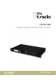
FIR DSP 408 digital speaker management system user manual
Musikhaus Thomann Thomann GmbH Hans-Thomann-Straße 1 96138 Burgebrach Germany Telephone: +49 (0) 9546 9223-0 E-mail: info@thomann.de Internet: www.thomann.de 11.02.
Table of contents Table of contents 1 General information.............................................................................................................. 1.1 Further information........................................................................................................ 1.2 Notational conventions................................................................................................. 1.3 Symbols and signal words..............................................................
General information 1 General information This user manual contains important information on the safe operation of the device. Read and follow all safety notes and all instructions. Save this manual for future refer‐ ence. Make sure that it is available to all persons using this device. If you sell the device to another user, be sure that they also receive this manual. Our products and user manuals are subject to a process of continuous development.
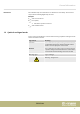
General information Instructions The individual steps of an instruction are numbered consecutively. The result of a step is indented and highlighted by an arrow. Example: 1. Switch on the device. 2. Press [Auto]. ð Automatic operation is started. 3. Switch off the device. 1.3 Symbols and signal words In this section you will find an overview of the meaning of symbols and signal words that are used in this manual.
Safety instructions 2 Safety instructions Intended use This device is intended to be used for amplification, mixing and playback of signals from musical instruments and microphones. Use the device only as described in this user manual. Any other use or use under other operating conditions is considered to be improper and may result in personal injury or property damage. No liability will be assumed for damages resulting from improper use.
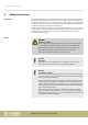
Safety instructions NOTICE! Possible damage due to installation of a wrong fuse The use of different types of fuses can cause serious damage to the unit. Fire hazard! Only fuses of the same type may be used.
Features 3 Features n n n n n n n n n n Digital speaker management system with FIR filter AD/DA converter 32-bit DSP 4 × XLR input sockets 8 × XLR output sockets Comprehensive setting options for optimal sound – Parametric Equalizer – Graphic Equalizer – High- and low-pass filters – Noise Gate – Limiter – Phase inversion USB connection for control via PC using the supplied software D-sub connector (RS232 / 485) for remote control of the device or cascading of several devices Ethernet interface (RJ45) fo
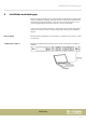
Installation and starting up 4 Installation and starting up Unpack and check carefully there is no transportation damage before using the unit. Keep the equipment packaging. To fully protect the product against vibration, dust and moisture during transportation or storage use the original packaging or your own packaging material suitable for transport or storage, respectively. Create all connections while the device is off. Use the shortest possible high-quality cables for all connections.
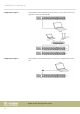
Installation and starting up Configuration example 2 The illustrations show schematically how one device or several devices can be inte‐ grated into a local area network (LAN). Configuration example 3 The illustrations show schematically how a device can be configured via the serial port.
Connections and controls 5 Connections and controls Front panel 1 Display 2 Buttons for direct selection of a parameter. Use [EXIT] to exit the Edit mode. 3 [ENTER / PARAMETER] Rotary switch 4 [EDIT] Buttons for selecting the Edit mode for the respective input channel. The set parameters of the selected channel appear in the display. 5 [INPUTS] Level meter for the input channels. The red [CLIP] LEDs indicate overloading (clipping). In this case, the level of the input signal is too high.
Connections and controls 9 [MUTE] Buttons for muting or unmuting the respective output channel 10 [MUTE] Buttons for muting or unmuting the respective input channel Rear panel 11 IEC chassis plug with fuse holder for the power supply 12 [POWER] Main switch.
Operating on the unit 6 Operating on the unit Starting the device Connect the device to the power grid and turn it on with the main switch to start operation. After a few seconds, the display indicates that a reset is in progress. The device is then ready for use. The display shows the model name and user preset cur‐ rently active. The device can only be operated directly with the buttons if it is not controlled via USB, LAN or the serial interface.
Operating on the unit User presets All device settings can be stored in up to 20 different user presets and recalled when needed. This allows you to easily restore your settings for different rooms or stage setups. Recalling user preset 1. Press [PRESET]. ð The menu ‘Load preset’ opens up. 2. Use the rotary switch to select a user preset between ‘U01’ and ‘U20’ or the default setting ‘F00’ . Press the rotary switch to confirm. ð The settings are being loaded. Saving user preset 1. Press [PRESET].
Operating on the unit Settings for the inputs 1. Press the [EDIT] button corresponding to the desired channel. ð The settings menu for the desired channel opens up. The display shows ‘GAIN’ . 2. In the default state of the menu, you can adjust the channel level in a range of -60 dB…+12 dB with the rotary switch. 3. To set additional parameters of the channel, press the corresponding button. Use the rotary switch to set the desired value of the parameter. Press the rotary switch to confirm.
Operating on the unit Settings for the outputs 1. Press the [EDIT] button corresponding to the desired channel. ð The settings menu for the desired channel opens up. The display shows ‘GAIN’ . 2. In the default state of the menu, you can adjust the channel level in a range of -60 dB…+12 dB with the rotary switch. 3. To set additional parameters of the channel, press the corresponding button. Use the rotary switch to set the desired value of the parameter. Press the rotary switch to confirm.
Operating on the unit Parameter Button Selection range Meaning ‘MIX’ [MATRIX] ‘T’ : ‘–60dB’ … ‘0dB’ For each of the input channels, which are assigned to the respective output channel, a level adjustment can be preset. ‘LIMIT’ 2× [DYNAMIC] ‘T’ : ‘–60dB’ … ‘+20dB’ Limiter parameters: Threshold, ratio, soft knee, attack, release.
Operating on the computer 7 Operating on the computer Install and start the software. 1. Insert the software CD into the disk drive of your Windows PC and start the installation programme that matches the device version. 2. Follow the instructions of the installation programme to completion. 3. Connect your PC to the device via a USB cable and turn on the device. ð The operating system detects the newly added USB device. 4. Open the PC programme. It automatically detects the connected device.
Operating on the computer Main menu Menu item Meaning ‘File’ Loading user presets and saving them to the PC; Data upload to the PC and data download to the device ‘Link’ Assignment of input to output channels ‘Copy’ Copying parameter settings from one input or output channel to another ‘Lock’ Changing device password ‘Setting ID / IP’ Changing the unique identification of the device in a series connection or the IP address for the inte‐ gration into a local network ‘In Select’ Select ‘AES / EB
Operating on the computer ‘Gain’ tab Range Meaning Display area The waveform of input and output channels is graphically displayed. Use the radio buttons ‘Inx’ and ‘Outx’ to set the inputs and outputs to be displayed. Control area Drag the faders with the mouse to adjust the levels for the input and output channels. The ‘Mute’ button mutes or unmutes the respective channel. The ‘Normal’ / ‘Inverse’ button inverts the phase of the respective channel by 180° when needed.
Operating on the computer ‘Gate’ tab Range Meaning Display area Shows the current settings of the noise gate for the respective channel, with a symbolic level indi‐ cator symbol appearing next to it for the input channels. The red dot in the curve corresponds to the current signal. Control area Drag the faders with the mouse to set the noise gate parameters for all input and output channels: Threshold, hold, attack, release.
Operating on the computer ‘Comp’ tab Range Meaning Display area Shows the current settings of the compressor function for the respective output channel, with a sym‐ bolic level indicator symbol appearing next to it for all output channels. The red dot in the curve cor‐ responds to the current signal. Control area Drag the faders with the mouse to set the compressor parameters for the output channels: Threshold, ratio, soft knee, attack, release, frequency, type.
Operating on the computer ‘Limit’ tab Range Meaning Display area Shows the current settings of the limiter for the respective channel, with a symbolic level indicator appearing next to it for all channels. Control area Drag the faders with the mouse to set the limiter parameters for all input and output channels: Threshold, attack, ratio, soft knee, release.
Operating on the computer ‘Delay’ tab Range Meaning Display area Shows the set delays for all in and output channels. Control area Drag the faders with the mouse to adjust the delay for the respective channel. Press one of the but‐ tons ‘ms’ , ‘m’ or ‘ft’ to select the unit to be used.
Operating on the computer ‘Matrix’ tab Range Meaning Display area Shows the current interconnection of input to output channels. Input and output channels can be renamed. Click on a functional area (e.g. ‘PEQ’ or ‘DELAY’ ) to open the tab where you can enter the corresponding parameters directly. Control area With a mouse click you can interconnect each input with each output channel. To each output channel, an input channel or the mix of several input channels can be freely assigned.
Operating on the computer ‘In’ tab Range Meaning Display area Use the radio buttons ‘Mag’ or ‘Phase’ to switch the diagram from Cartesian coordinates (level vs. frequency) to polar coordinates (angle vs. frequency). Use the radio button ‘SHOW ALL EQ’ to display the parameters for all nine frequency bands.
Operating on the computer ‘Out’ tab FIR DSP 408 27
Operating on the computer Range Meaning Display area Use the radio buttons ‘ Mag’ or ‘Phase’ to switch the diagram from Cartesian coordinates (level vs. frequency) to polar coordinates (angle vs. frequency). Use the radio button ‘SHOW ALL EQ’ to display the parameters for all nine frequency bands.
Technical specifications 8 Technical specifications Inputs Outputs Type XLR chassis socket (balanced) Level +18 dBu (max.) Impedance 1 MΩ (stereo), 500 kΩ (mono) Type XLR chassis plug (balanced) Level +20 dBu (max.) Impedance < 500 Ω Frequency response 20 Hz … 20 kHz, –0.3 dBu THD < 0.
Plug and connection assignment 9 Plug and connection assignment Introduction This chapter will help you select the right cables and plugs to connect your valuable equipment in such a way that a perfect sound experience is ensured.
Protecting the environment 10 Protecting the environment Disposal of the packaging material For the transport and protective packaging, environmentally friendly materials have been chosen that can be supplied to normal recycling. Ensure that plastic bags, packaging, etc. are properly disposed of. Do not just dispose of these materials with your normal household waste, but make sure that they are collected for recycling. Please follow the notes and markings on the packaging.
Notes digital speaker management system 32
Notes FIR DSP 408 33
Notes digital speaker management system 34
Musikhaus Thomann · Hans-Thomann-Straße 1 · 96138 Burgebrach · Germany · www.thomann.