TTP 248M THERMAL TRANSFER / DIRECT THERMAL BAR CODE PRINTER SERVICE MANUAL
TTP-248M Bar Code Printer Service Manual TABLE OF CONTENT 1. Foundamentals About the System .............................................................................. 1 Printer Overview...................................................................................................... 1 Front View ........................................................................................................ 1 Rear View ..........................................................................................
TTP-248M Bar Code Printer Service Manual 4.2 Replacing the Mainboard ................................................................................ 43 4.3 Replacing the Power Supply Unit .................................................................... 44 4.4 Replacing the Ribbon Rewind Spindle ............................................................ 45 4.5 Replacing Ribbon Supply Spindle ................................................................... 48 4.6 Replacing Label Supply Spindle .....
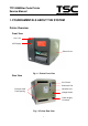
TTP-248M Bar Code Printer Service Manual 1. FOUNDAMENTALS ABOUT THE SYSTEM Printer Overview Front View Aux. LED LCD Display Printer Cover Fig. 1.1 Printer Front View Rear View Aux. Buzzer Centronics Port External Label RS-232C Port Feed Opening Voltage Switch Power Supply Connector Fig. 1.
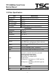
TTP-248M Bar Code Printer Service Manual 1.2 Pinter Specification Item Specification Printing Mode Thermal transfer and direct thermal Resolution 203 DPI Max. Print Length 999 mm Max.
TTP-248M Bar Code Printer Service Manual TPH ROHM KF2004-GL41D 550Ω Stepping Motor Mitsumi 24V 7.5 Degrees 4Ω Japan Servo KH56KM 2u023 1.80,24V,0.
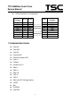
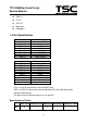
TTP-248M Bar Code Printer Service Manual RS-232 Interface Pin Configuration: Host Function 9 Pin 25 Pin RxD TxD DTR GND DSR RTS CTS 2 3 4 5 6 7 8 9 Pin 1 2 3 4 5 6 7 8 9 3 2 20 7 6 4 5 1.3 Available Bar Codes Code 39 Code 39C Code 93 Code128UCC Code128 subsets A.B.
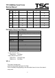
TTP-248M Bar Code Printer Service Manual EAN-14 ITF14 PDF-417 Maxicode DataMatrix 1.4 Text Specification Font Font 1 Font 2 Font 3 Font 4 Font 5 Font 6 Font 7 Font 8 Width x Length 8x12 12x20 16x24 24x32 32x48 14x19 OCRB 21x27 OCRB 14x25 OCRA Font EAN 1 EAN 2 EAN 3 EAN 4 EAN 5 EAN 6 EAN 7 EAN 8 EAN 9 EAN 10 Width x Length 7x10 14x22 21x33 28x43 35x52 42x64 49x74 56x85 63x97 70x107 Font 1 to Font 8 are all build-in fonts and BF1 fonts.
TTP-248M Bar Code Printer Service Manual BF2 X BF3 X BF4 X X X X X VF1 X VF2 X VF3 X VF4 X X X X X X X X File Head of Font ( Fixed 32bytes ) Offset 0 Offset 1 Offset 2 Offset 3 Offset 4 Offset 5-6 Offset 7-8 Offset 9-10 Offset 11-12 Offset 13 Offset 14 Offset 15-16 Offset 17-18 Offset 19-31 B->Bitmap font 0->Fixed pixel 1->Variable Pixel 0->Singed Byte Decode 1->Double Byte Decode Decode by table 0-> None 1->Italic Font Height Font Width Font decode start Font decode end Font decode typ
TTP-248M Bar Code Printer Service Manual BF3~4 VF3~4 Decode Table (char low byte) (char high byte) (offset 4 bytes ==> file start to font data) The font with decade table, the previous two bytes of every word is the code of the word, and the later four bytes is the displacement from the file head to the position of the data of the word.
TTP-248M Bar Code Printer Service Manual 2. SUPPLY SPECIFICATIONS 2.1 Types of Paper Two types of media are available for TTP-248M/2410M : label and ticket. In TTP-248M/2410M, there are two types of sensors for paper : gap sensor and black mark sensor. Label and ticket can be further classified into direct thermal type or thermal transfer type. 2.2 Specification Item Specification Type Label (Continuous, die-cut, fan-fold, ticket, Tag etc.) Label Width 19~118 mm ( 0.7”~4.
TTP-248M Bar Code Printer Service Manual 2.3 Ribbon Specification Item Specification Ribbon Shape Spool type Ribbon Width 25.4~114.3 mm Ribbon Length 450 m Diameter Less than 3.5” ( 89 mm) Roll Up Method Print surface wound outside as standard. Note: The maximum length of ribbon depends on its thickness and core outside diameter. The formula below defines the correlation between ribbon roll length and ribbon core diameter. (D 2 d 2 ) L= where 4t , L = Ribbon length D = Max.
TTP-248M Bar Code Printer Service Manual 3. CIRCUIT DESCRIPTION 3.1 MCU L1 2 U 32 1 2 V CC C 12 V- R 56 U 6E R 18 10 K 8 V CC 3 B C8 0. 1uF B C9 0. 1uF B C1 0 0. 1uF V det TM V CC D I1 D I2 D I3 D I4 /R ESET_PH /LAT STB1 STB2 V det STB3 TM STB4 C LK B C2 1 B C2 2 0. 1uF 0. 1uF B C2 3 B C2 4 0. 1uF 0. 1uF B C2 7 B C2 8 0. 1uF 0. 1uF V CC B C3 0 0. 1uF B C3 1 B C3 2 0. 1uF 0. 1uF C 26 0. 1uF B C1 1 0. 1uF B C1 2 B C1 3 0. 1uF 0. 1uF B C1 4 B C1 5 0. 1uF 0. 1uF 74 HC T14 B C2 9 0.
TTP-248M Bar Code Printer Service Manual The figure below shows the PCB system area: Communication port Decoder System Print Head Connector External Memory Connector MCU Memory System Power System Sensor Connector Motor System Option I/O Cutter System Fig. 3.
TTP-248M Bar Code Printer Service Manual 3.
TTP-248M Bar Code Printer Service Manual 13
TTP-248M Bar Code Printer Service Manual 14
TTP-248M Bar Code Printer Service Manual 15
TTP-248M Bar Code Printer Service Manual 16
TTP-248M Bar Code Printer Service Manual 17
TTP-248M Bar Code Printer Service Manual 18
TTP-248M Bar Code Printer Service Manual 19
TTP-248M Bar Code Printer Service Manual 20
TTP-248M Bar Code Printer Service Manual 3.3 Reset Circuit VCC VCCL VCC 3 R3 3. 0K VDD 4 5 R2 3. 4K C77 0. 1uF GND R130 10 K U10 VCC3 /RST VCC5 GND VCCA 1 RESET 2 GND LTC1 72 8 C78 0. 1uF GND GND Fig. 3.3 Reset Circuit This is the reset circuit. The LTC1728IC detects three kinds of DC Voltage (5V, 3V and 1.9V). VCC3 (VCC, DC3V) input threshold is 3.086 VCC5 (VDD, DC5V) threshold is 4.675. R2 VCCA ( R1+R3 ×VCCL, DC1V ) is 1.
TTP-248M Bar Code Printer Service Manual 3.4 Memory System G ND J 1 1 3 5 7 9 11 13 15 17 19 21 23 25 27 29 /R ESET31 /O E 33 D1 35 D3 37 D5 39 D7 41 D9 43 D 11 45 D 13 47 D 15 49 V CC B C4 5 0. 1uF B C3 9 0. 1uF B C3 8 0. 1uF B C3 7 6 0. 1uF B C3 5 0. 1uF B C3 4 0. 1uF B C4 1 0. 1uF B C4 0 0. 1uF G ND V CC B C4 2 B C4 6 0. 1uF B C4 4 0. 1uF B C4 3 0. 1uF 0.
TTP-248M Bar Code Printer Service Manual 3.5 Decoder Circuits USE CPLD to decode. 3.
TTP-248M Bar Code Printer Service Manual 0x00000000 2-Gbytes virtual space, cacheable (write-back/write-through) 0x80000000 0.5-Gbytes fixed physical space, Area P1 cacheable (write-back / write-through) 0.5-Gbytes fixed physical space, Area P2 non-cacheable 0.5-Gbytes virtual space, Area P3 cacheable (write-back / write-through) 0.5-Gbytes control space, Area P4 non-cacheable Table 1.
TTP-248M Bar Code Printer Service Manual 0xA8100000 0xA8200000 0xA8300000 0xA8400000 0xA8500000 0xA8600000 0xA8700000 Ribbon Near End Data Register (1 byte) Centronics Data Register (1 byte) TPH Data Area 1 Register (1 byte) TPH Data Area 2 Register (1 byte) TPH Data Area 3 Register (1 byte) TPH Data Area 4 Register (1 byte) Cutter Control Register (1 byte) 0xA8800000 N/C | 0xA88FFFFF 0xA8900000 LCD Control Register (1 byte) 0xA8A00000 0xAC000000 | 0xAC3FFFFF 0xB0000000 | 0xB3FFFFF 0xB4000000 | 0xB7FFFFF
TTP-248M Bar Code Printer Service Manual 3.
TTP-248M Bar Code Printer Service Manual 3.8 Power Down Sensor 1. 9V VCCL R118 1 R116 R117 1 1 U21 8 7 6 5 C21 VDD Ip k VCC Vref SW SWE TC GND 34 06 3 10 uF 1 2 3 4 L1 8 L2 1 33 0u C8 10 0p 0 D10 SS14 C72 15 00 pF C16 0. 1u R96 C66 47 0u C69 10 0u /35 V 1. 9K R122 3. 6K C76 10 0u F VCC R7 4. 42K GND 1. 5V U20 SI-80 33 JD 14 R4 C22 22 0u F 30 .9k R6 10 M 1 GND Vin R5 4. 42k SW Vos 2 L1 7 L2 0 10 0u 0 3. 3V VCC JP29 2 1 4 2PIN G ND R8 3.
TTP-248M Bar Code Printer Service Manual 3.9 Print Head VDD R44 R45 R46 R47 10 K 10 K 10 K 10 K 9 CLK 5 /LAT 74 LS14 CONNECT BY VDD 2 3 U7C STB2 5 U7D 4 6 9 8 6 6 10 U8E 1 U7B STB1 STB4 2 4 74 HCT1 4 74 HCT1 4 11 U8F U7A STB3 8 U8C GND 74 HCT1 4 74 HCT1 4 74 HCT1 4 DI1 13 DI2 74 HCT1 4 DI3 U8A 4 19 20 15 16 13 14 7 8 74 HCT1 4 1 U8B 3 DI4 10 12 JP18 A ROHM_ KF20 04_ GL41 A VDD U8D BC3 3 0.
TTP-248M Bar Code Printer Service Manual 3.10 Motor System Circuit STEP PHASE INA_R /INA_R INB_R /INB_R 1 2 ON ON ON 3 4 ON ON ON ON ON Table 5. Stepping Motor Pattern VMM C60 EN_MA EN_MB MOTER_C MGND 22 00 uF MGND 5 C29 0. 1u F Vs U13 IN1 IN2 C28 0. 1u F 1 R103 22 K 2 C56 15 00 pF 20 SYNC R/C VSENSE2 REF2 OSC VSENSE1 REF1 BOOT2 Vref SENSE NC NC NC NC G ND G ND G ND G ND C48 22 0n F 15 STEPPING_ MOTOR 14 R99 8. 2 JP14 1 2 3 4 C41 15 nF C52 0.
TTP-248M Bar Code Printer Service Manual 3.11 Sensor Circuits Ribbon Near End Sensor The voltage of sender (PIN 3) is about 1.18V (1.17V~1.19V). When the sensor detects the black area, the voltage of receiver (PIN 2) is≧ 2.10V. When the sensor detects the white area, the voltage of the receiver (PIN 2) is≦ 1.26V. U3F U2/1 19 12 VCC 13 R64 10 0 74 HC14 R67 10 0 JP2 4 3 2 1 R25 10 K GND RNE_ END Fig. 3.9 Ribbon Near End Sensor Circuit GAP Sensor 1. Selecting MANUAL GAP and adjust the tension.
TTP-248M Bar Code Printer Service Manual between 4.4V~3.7V. 2. Selecting AUTO GAP to detect label will get a value of tension, and then selecting the MANUAL GAP. When sensor detects white paper: LCD displays Reflect the voltage of receiver (PIN 3)≦2.10V When sensor detects the Black mark or does not detect paper: LCD displays Not Reflected the voltage of receiver (PIN 3)≧1.26V VCC JP12 R66 10 U1/1 2 U3E GAP_SENSER 10 0 R27 4.
TTP-248M Bar Code Printer Service Manual Fig. 3.11 Peel-off Sensor Circuit Case Sensor The voltage of sender is about 1.18V (1.17V~1.19V) When sensor detects upper cover, the voltage of receiver (PIN 2) is≧2.10V When sensor does not detect upper cover, the voltage of receiver is ≦1.26V VCC R76 10 0 R75 10 0 JP16 4 3 2 1 U4C 6 CASE_SENS 5 R51 10 K 74 HC14 GND 4PIN Fig. 3.
TTP-248M Bar Code Printer Service Manual 2. Selecting AUTO RIBBON to detect ribbon will get a value of tension, and then selecting the MANUAL Ribbon. When sensor detects ribbon: LCD displays Not Through the voltage of receiver (PIN 4)≦1.26V When sensor detects no ribbon: LCD displays Through the voltage of receiver (PIN 4)≧2.10V. VCC R77 10 0 JP22 1 2 3 4 5 R_END U4D R_SENS 8 REND_SENS 9 74 HC14 R9 10 K GND Fig. 3.14 Ribbon End Sensor Circuit 3.
TTP-248M Bar Code Printer Service Manual U19 is used for industrial long-distance asynchronous communication;U19 is optional. 3.
TTP-248M Bar Code Printer Service Manual 3.14 Cutter Drive System Fig. 3.17 Cutter Drive Circuit JP33Pin 2 and 4 connect DC motor; pin 3 connects sensor. Pin /BK Cutter is used to stop DC motor. PHASE is used to control obversion and reverse. Pin EN_CUTTER is used to enable Cutter. Pin CTSENS is the sensor of cutter tab.
TTP-248M Bar Code Printer Service Manual 3.15 PIN Switch Circuits JP28 1 2 JP3/9 JP3/1 開關 2PIN Fig. 3.18 LTC490 and RS232 pin switch VCC R95 10 K JP27 2 1 U1/7 2PIN GND Fig. 3.19 Download boot program to on-board Flash memory pin switch 3.16 Connector Circuits VCC TCK TDO TDI TMS JP1 1 2 3 4 5 6 GND JP1 Fig. 3.
TTP-248M Bar Code Printer Service Manual A[1.. 24] CS0 RESET U23/28 /OE&/RD GND J1 1 A2 3 A4 5 A6 7 A8 9 A10 11 A12 13 A14 15 A16 17 A18 19 A20 21 A22 23 VCC 25 A24 27 29 /RESET31 /OE 33 D1 35 D3 37 D5 39 D7 41 D9 43 D11 45 D13 47 D15 49 2 4 6 8 10 12 14 16 18 20 22 24 26 28 30 32 34 36 38 40 42 44 46 48 50 A1 A3 A5 A7 A9 A11 A13 A15 A17 A19 A21 A23 VCC /WE D0 D2 D4 D6 D8 D10 D12 D14 CS2 CS3 /WEO/DQMLL 50 PIN_P2 GND D[0.. 15] Fig. 3.
TTP-248M Bar Code Printer Service Manual U13/6 OUT1 U13/4 STEPPING_ MOTOR R99 8. 2 JP14 1 2 3 4 OUT2 C52 0. 01u F 4PIN U12/6 OUT1 R100 8. 2 C53 0. 01u F U12/4 OUT2 Fig. 3.
TTP-248M Bar Code Printer Service Manual 3.17 Optional Items Circuits The following circuits provide optional detecting message or input/output control. AD1 AD2 C80 C81 0. 1uF R135 10 0 D11 D12 0. 1uF R136 10 0 AVCC JP25 D13 D14 AVCC 2 1 1N41 48 R132 AVSS 1N41 48 1K R131 1N41 48 2PIN R134 1K AVSS 1N41 48 1K R133 2PIN 1K VCC VMM BUZZER_O JP11 2 1 R40 10 K U4F 13 JP26 2 1 Q1 BUZZER HSC945 R71 12 10 0 74 HC14 GND Fig. 3.
TTP-248M Bar Code Printer Service Manual 4. MACHANISM 4.1 Remove the Covers and LCD Panel 1. Open Top Right Side Cover. 2. Loosen the four screws used to fix Main Frame and Top Right Side Cover.
TTP-248M Bar Code Printer Service Manual 3. Loosen the three screws on Top Left Side Cover. Screws 4. Remove Top Right Side Cover and Top Left Side Cover. 5. Remove the LCD Panel and remove the Lower Front Cover to the right side.
TTP-248M Bar Code Printer Service Manual Screw LCD Panel Screw Lower Front Cover 42
TTP-248M Bar Code Printer Service Manual 4.2 Replacing the Mainboard 1. Disconnect all harnesses. 2. Remove the seven screws on Mainboard, two hexagon screws of serial port and two screws of parallel port. Mainboard Screw Screw Screw Screw Parallel Port Screw Serial Port 3. Replace the Mainboard. 4. Reassemble in the reverse procedures.
TTP-248M Bar Code Printer Service Manual 4.3 Replacing the Power Supply Unit 1. Disconnect all harnesses. Power Supply Unit 2. Turn the printer upside down to loosen the two screws of the Power Supply Unit on the bottom of the printer. Two screws Screws 3. Replace the Power Supply Unit. 4. Reassemble in the reverse procedures.
TTP-248M Bar Code Printer Service Manual 4.4 Replacing the Ribbon Rewind Spindle 1. Refer to 4.3 to remove the Power Supply Unit. 2. Remove the E-ring of the Label Rewind Spindle and the Label Rewind Spindle with belt. Belt E-ring of Label Rewind Spindle 3. Loosen the four screws of the Stepping Motor Frame. Remove the stepping motor assembly and its belts.
TTP-248M Bar Code Printer Service Manual Screws Screws Pulley ws 4. Remove the E-ring of pulley. And then, remove the pulley. Pulley E-ring 5. Loosen the three screws on the Cam Spindle Support Plate.
TTP-248M Bar Code Printer Service Manual Screws 6. Replace the Ribbon Rewind Spindle. 7. Reassemble in the reverse procedures after replacing.
TTP-248M Bar Code Printer Service Manual 4.5 Replacing Ribbon Supply Spindle 1. Remove the four screws of the Ribbon Supply Spindle. Screws Screws 2. Remove the shaft bearing. 3. Replace the Ribbon Supply Spindle.
TTP-248M Bar Code Printer Service Manual 4. Reassemble in the reverse procedures after replacing.
TTP-248M Bar Code Printer Service Manual 4.6 Replacing Label Supply Spindle 1. Refer to 4.2 to remove the Mainboard. 2. Remove the three screws of the Label Supply Spindle. Screws 3. Remove the four screws of the fixing plate. Screws Screws 4. Replace the Label Supply Spindle.
TTP-248M Bar Code Printer Service Manual 5. Reassemble in the reverse procedures after replacing.
TTP-248M Bar Code Printer Service Manual 4.7 Replacing Label Rewind Spindle 1. Refer to 4.3 to remove the Power Supply Unit. 2. Remove the E-ring and the pulley of the Label Rewind Spindle. E-ring 3. Remove the three screws of the Label Rewind Spindle. Screws 4. Remove the four screws of the fixing plate.
TTP-248M Bar Code Printer Service Manual Screws Screws 5. Replace the Label Rewind Spindle. 6. Reassemble in the reverse procedures after replacing.
TTP-248M Bar Code Printer Service Manual 4.8 Replacing Platen 1. Refer to 4.1 to remove the Top Right and Left Side Covers. 2. Release the Print Head Lift Lever. 3. Remove the screw and the Stripper/Rewind Plate. Print Head Lift Lever Screw Stripper/Rewind Plate 4. Remove the Tab Core, Support Plate and Right Shaft Bearing. Right Shaft Bearing Support Plate Tab Core 5. Remove the two screws on the Gear.
TTP-248M Bar Code Printer Service Manual Screws 6. Remove the Platen and Left Shaft Bearing. Left Shaft Bearing Platen 7. Reassemble in the reverse procedures after replacing.
TTP-248M Bar Code Printer Service Manual 4.9 Replacing Motor 1. Loosen the four fixing screws on the Motor. Screws Screws 2. Disconnect the harness from the Motor Disconnect the harness 3. Replace the Motor.
TTP-248M Bar Code Printer Service Manual 4. Reassemble in the reverse procedures after replacing.
TTP-248M Bar Code Printer Service Manual 4.10 Replacing Print Head 1. Remove the screws on the Print Head. Screw 2. Disconnect the two Printer Harnesses. 3. Replace the Print Head. 4. Reassemble in the reverse procedures after replacing.
TTP-248M Bar Code Printer Service Manual 4.11 Replacing Print Head Pressure Adjustment Knob 1. Open the Right Side Cover and Right Side Plate. 2. Remove the Nut from the Print Head Lift Lever. Then remove the Print Head Lift Lever. Nut 3. Remove the 2 screws these are on the TPH switch plate. Screws 4. Remove the four screws these are on the Right Side Fixing Plate, Right Side Fixing Plate, and then, remove the Print Head Adjustment Knob assembly.
TTP-248M Bar Code Printer Service Manual Screws Screws 5. Remove A.B.C.D in order. 6. Loosen M4 screw, knob E and F. M4 screw Knob F E D C B A 7. Reassemble in the reverse procedures after replacing.
TTP-248M Bar Code Printer Service Manual 4.12 Replacing Gap/Black Mark Sensor 1. Disconnect the wires of Gap/Black Mark Sensor. 2. Refer to 4.8 to remove the Stripper/Rewind Plate. 3. Loosen two screws on Print Mechanism Lower Frame. Print Mechanism Lower Frame Screws 4. Loosen the two screws on the bottom of the Gap/Black Mark Sensor.
TTP-248M Bar Code Printer Service Manual 5. Remove the screw on the main frame. The Gap/Black Mark Sensor assembly is separated into upper part and lower part. Screws 6. Push the upper part to the through the hole against to the Print Mechanism Lower Frame, place the upper part upside down, pull the lower part to the right side first, and then, pull out the upper part.
TTP-248M Bar Code Printer Service Manual 7. Reassemble in the reverse procedures after replacing.
TTP-248M Bar Code Printer Service Manual 4.14 Replacing Print Head Lift Lever Sensor 1. Open the Top Left Side Cover. 2. Remove the Curly plastic pipe, and pull out the harness. 3. Disconnect all harness of Print Head Lift Lever Sensor. Remove the 2 screws of Print Head Lift Lever Sensor. Curly plastic pipe Screws 4. Remove Print Head Lift Lever Sensor. 5. Reassemble in the reverse procedures after replacing.
TTP-248M Bar Code Printer Service Manual 5. TROUBLESHOOTING 5.1 Troubleshooting The following guide lists the most common problems that may be encountered when operating this bar code printer. If the printer still does not function after all suggested solutions have been invoked, please contact the Customer Service Department of your purchased reseller or distributor for assistance. Phenomenon No ribbon Cause of Errors 1. Running out of ribbon 2. The ribbon is installed incorrectly. 3.
TTP-248M Bar Code Printer Service Manual 2. Labels may be stuck in side print mechanism. Carriage open The printer carriage is open. Memory full ( FLASH / DRAM ) gap/black mark sensor. 2. Remove the stuck label. Please close the print carriage. Delete unused files in the FLASH/DRAM. 1. Please reset the serial port setting. 2. Please replace the cable with pin to pin assignment. The space of FLASH/DRAM is full. 1. The serial port setting is not consistent between No printout printing host and printer.
TTP-248M Bar Code Printer Service Manual 5.3 Self-test To initiate the self-test mode, depress the MENU button. Press MENU button to scroll the cursor to Printer test. Press EXE button to enter the submenu and press MENU button to “Printer Config”. item. Press EXE button to print printer internal setting. In self-test, a check pattern is used to check the performance of the print head. Following the check pattern, the printer prints internal settings as listed below: 1.
TTP-248M Bar Code Printer Service Manual 5.6 Cleaning Print Head 1. Switch off and unplug the power cord. Allow the printhead to cool for a minimum of one minute. 2. Open the printer cover. 3. Remove the screw by the side of the carriage release lever. 4. Open the printer carriage release lever. 5. Remove the media and ribbon (If loaded). 6. Clean the print head element with a head cleaner pen or use a cotton swab and 100% ethanol to clean the print head surface. 7.
TTP-248M Bar Code Printer Service Manual UPDATE HISTORY Date Content Editor 2007/1/17 1. Modify TPH part no. Camille 2007/1/24 2. Cancel guillotine cutter part no. 1. Add cutter driver IC A3952SB (Non-RoHS) part no. Camille 2007/1/25 1. Modify the cutter part no. 2. Modify the memory card part no. 3. Add the Internal print server (C) part no. 1. Modify the External Ethernet print server (C) part no. 1. Update TSC e-mail address 2. Update 6.6 section: cleaning print head 1.
TSC Auto ID Technology Co., Ltd. Corporate Headquarters 9F., No.95, Minquan Rd., Xindian Dist., New Taipei City 23141, Taiwan (R.O.C.) TEL: +886-2-2218-6789 FAX: +886-2-2218-5678 Web site: www.tscprinters.com E-mail: printer_sales@tscprinters.com tech_support@tscprinters.com Li Ze Plant No.35, Sec. 2, Ligong 1st Rd., Wujie Township, Yilan County 26841, Taiwan (R.O.C.