TDP-225/ TDP-225W/ TDP-324/ TDP-324W Series DIRECT THERMAL BAR CODE PRINTER USER’S MANUAL
Contents Copyright Declaration....................................... i 1. Introduction ........................................... ii 1.1 Product Introduction ............................................................................... ii 1.2 Compliances ............................................................................................ ii 2. Operations Overview ..................................... 1 2.1 Unpacking and Inspection .................................................................
4.3.3 Printer Initialization...................................................................... 29 4.3.4 Set Black Mark Sensor as Media Sensor and Calibrate the Black Mark Sensor .......................................................................................... 30 4.3.5 Set Gap Sensor as Media Sensor and Calibrate the Gap Sensor 30 4.3.6 Skip AUTO.BAS ............................................................................ 31 5. Troubleshooting ........................................ 32 5.
Copyright Declaration Information in this subject to change without notice and does not represent a commitment on the part of TSC Auto ID Technology Co., Ltd.. No part of this manual may be reproduced or transmitted in any form by any means, for any purpose other than the purchaser’s personal use, without the expressed written permission of TSC Auto ID Technology Co., Ltd..
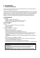
1. Introduction 1.1 Product Introduction Thank you for purchasing TSC bar code printer. Although the printer has a small footprint, it delivers reliable, superior performance. This printer provides direct thermal printing at user selectable speed of: 2.0, 3.0, 4.0 or 5.0 ips for 203 dpi; 2.0, 3.0 or 4.0 ips for 300 dpi. It accepts roll feed, die-cut, and fan-fold media with gap or black mark. All common bar codes formats are available.
WARNUNG! GEFÄ HRLICHE BEWEGLICHE TEILE – FINGER UND ANDERE KÖ RPERTEILE FERNHALTEN! VORSICHT! EXPLOSIONSGEFAHR BEI ERSATZ DER BATTERIE DURCH UNZULÄ SSIGEN TYP. VERBRAUCHTE BATTERIEN IMMER VORSCHRIFTSGEMÄ SS ENTSORGEN! Note: The maximum printing ratio per dot line is 15% for this printer. To print the full web black line, the maximum black line height is limited to 40 dots, which is 5mm for 203 DPI resolution printer and 3.3mm for 300 DPI resolution printers..
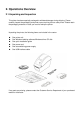
2. Operations Overview 2.1 Unpacking and Inspection This printer has been specially packaged to withstand damage during shipping. Please carefully inspect the packaging and printer upon receiving the bar code printer. Please retain the packaging materials in case you need to reship the printer. Unpacking the printer, the following items are included in the carton.
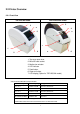
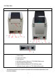
2.2 Printer Overview 2.2.1 Front View TDP-225/324 model TDP-225W/324W model 3 3 4 4 5 5 7 1 1 6 2 2 1. Top cover open lever 2. MicroSD card socket 3. Media view window 4. LED indicator 5. Feed button 6. Paper exit chute 7. LCD display (Option for TDP-225/324 model) * Recommended MicroSD card specification. SD card spec SD card capacity Approved SD card manufacturer V1.0, V1.1 MicroSD 128 MB Transcend, Panasonic V1.0, V1.1 MicroSD 256 MB Transcend, Panasonic V1.0, V1.
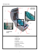
2.2.2 Interior View 2 (TDP-225W /324W model) 4 1 5 9 6 7 2 (TDP-225/324 model) 3 8 1. Top cover 2. Media holder 3. Media guide 4. Printhead 5. Gap sensor (receiver) 6. Gap sensor (transmitter) 7. Platen roller 8. Black mark sensor 9.
2.2.3 Rear View TDP-225/324 model TDP-225W/324W model 5 1 2 3 4 1 2 3 7 1. Power switch 2. Power jack socket 3. USB interface 4. RS-232C interface (Option for TDP-225W/324W mode) 5. Fan-fold paper entrance chute 6. Ethernet interface (Option for TDP-225/324 model) 7. USB host (Factory option for TDP-225W/324W model) Note: The interface picture here is for reference only. Please refer to the product specification for the interfaces availability.
3. Setup 3.1 Setting Up the Printer 1. Place the printer on a flat, secure surface. 2. Make sure the power switch is set to “off”. 3. Connect the printer to the computer with the provided USB cable. 4. Plug the power cord into the AC power cord socket at the rear of the printer, and then plug the power cord into a properly grounded power outlet. Note: Please switch OFF printer power switch prior to plug in the power cord to printer power jack. 3.2 Loading the Media 3.2.1 Loading the Media 1.
3. Separate the media holders to the label roll width. TDP-225/324 model TDP-225W/324W model 4. Place the roll between the holders and close them onto the core. TDP-225/324 model TDP-225W/324W model Sensor Platen roller 5. Place the paper, printing side face up, through the media guides, media sensor and place the label leading edge onto the platen roller.
6. Close the top cover gently and make sure the cover latches securely. TDP-225/324 model TDP-225W/324W model 7. Use “Diagnostic Tool” to set the media sensor type and calibrate the selected sensor.
Note: * Please calibrate the gap/black mark sensor when changing media. * Please refer to videos on TSC YouTube or driver CD.
3.2.2 Loading External Media (For TDP-225/324 model only) 1. Open the printer’s top cover and separate the media holders to fit the media width. 2. Press down the media holder lock switch to fix the media holder. 3. Feeds the media through the rear external label entrance chute. And place the paper, printing side face up, through the media guides, media sensor and place the label leading edge onto the platen roller. Rear external label entrance 4. Close the top cover gently. 5.
10
3.2.3 Loading Media in Peel-off Mode (Option) 1. Refer to section 3.2.1 to load the media. 2. Open the top cover and peel-off panel after calibrated the sensor. Peel-off panel 3. Lead the media through the backing paper opening, beneath the peel-off roller. Peel-off roller Backing paper opening 4. Push the peel-off panel back to the printer.
5. Close the top cover gently. 6. Press the FEED button to test. Backing paper (Liner) Note: Please calibrate the gap/black mark sensor when changing media.
3.2.4 Loading Media in Cutter Mode (Option) 1. Refer to section 3.2.1 to load the media. 2. Lead the media through the cutter paper opening. Cutter paper opening 3. Close the top cover gently. 4. Use “Diagnostic Tool” to set the media sensor type and calibrate the selected sensor.
Note: * Please calibrate the gap/black mark sensor when changing media. * Cutter module specification: Full cut: Paper thickness: 0.06 ~ 0.19 mm, 200,000 cuts Partial cut: Paper thickness: 0.06 ~ 0.12 mm, 500,000 cuts * Except for the linerless cutter, all regular/heavy duty/care label cutters DO NOT cut on media with glue.
3.3 Diagnostic Tool The Diagnostic Utility is enclosed in the CD disk \Utilities directory or can be downloaded from www.tscprinters.com website. The Diagnostic Utility is a toolbox that allows users to explore the printer's settings and status; change printer settings; download graphics, fonts, and firmware; create printer bitmap fonts; and to send additional commands to the printer. Using this convenient tool, you can explore the printer status and settings and troubleshoot the printer.
3.3.2 Printer Function (Calibrate sensor, Ethernet setup, RTC setup………) 1. Select the PC interface connected with bar code printer. 2. Click the “Function” button to setting. 3. The detail functions in the Printer Function Group are listed as below.
3.4 Setting Ethernet by Diagnostic Utility (Option for TDP-225/324 model) The Diagnostic Utility is enclosed in the CD disk \Utilities directory or can be downloaded from www.tscprinters.com website. Users can use Diagnostic Tool to setup the Ethernet by USB and Ethernet interfaces. The following contents will instruct users how to configure the Ethernet by these interfaces. 3.4.1 Using USB interface to setup Ethernet interface 1. Connect the USB cable between the computer and the printer. 2.
3.4.2 Using Ethernet interface to setup Ethernet interface 1. Connect the computer and the printer to the LAN. 2. Turn on the printer power. 3. Start the Diagnostic Utility by double clicks on the icon. Note: This utility works with printer firmware V6.00 and later versions. 4. Select “Ethernet” as the interface then click on the “Setup” button to setup the IP address, subnet mask and gateway for the on board Ethernet. 5.
“Set IP” to take effect the settings. Users can also change the “Printer Name” by another model name in this fields then click “Set Printer Name” to take effect this change. Note: After clicking the “Set Printer Name” or “Set IP” button, printer will reset to take effect the settings. 8. Click “Exit” button to exit the Ethernet interface setup and go back to Diagnostic Tool main screen.
3.5 Install MicroSD Memory Card 1. Open the SD memory card cover. 2. Insert the MicroSD card into the socket. 3. Close the memory card cover. * Recommended SD card specification. SD card spec SD card capacity Approved SD card manufacturer V1.0, V1.1 MicroSD 128 MB Transcend, Panasonic V1.0, V1.1 MicroSD 256 MB Transcend, Panasonic V1.0, V1.1 MicroSD 512 MB Transcend, Panasonic V1.0, V1.1 MicroSD 1 GB Transcend, Panasonic V2.
- Folders/files stored in the SD card should be in the 8.
3.6 Mount the Printer on the Wall There are three holes in the bottom of printer. Printer can be mounted on the wall by the 3.0mm~3.5mm screw head screws.
3.7 Using the PC USB Keyboard with Printer USB Host Interface (Factory option for TDP-225W/324W model) 1. Turn off the printer power. 2. Plug in the PC USB keyboard into printer USB host interface. 3. Turn on the printer power. 4. After pressing the F1 key of the keyboard, the printer LCD will display as following. File List > DRAM FLASH 5.
4. LED and Button Functions This printer has one button and one three-color LED indicator. By indicating the LED with different color and pressing the button, printer can feed labels, pause the printing job, select and calibrate the media sensor, print printer self-test report, reset printer to defaults (initialization). Please refer to the button operation below for different functions. 4.
Power on utilities The LED color will be changed as following pattern: LED color Amber Red Amber Green Functions (5 blinks) (5 blinks) (5 blinks) 1. Gap / black mark sensor calibration Release 2. Gap / black mark sensor calibration, Green/Amber Red/Amber Solid green (5 blinks) (5 blinks) Release Self-test and enter dump mode 3. Printer initialization Release 4. Set black mark sensor as media Release sensor and calibrate the black mark sensor 5.
4.3.2 Gap/Black Mark Calibration, Self-test and Dump Mode While calibrate the gap/black mark sensor, printer will measure the label length, print the internal configuration (self-test) on label and then enter the dump mode. To calibrate gap or black mark sensor, depends on the sensor setting in the last print job. Please follow the steps below to calibrate the sensor. 1.Turn off the power switch. 2. Hold on the button then turn on the power switch. 3. Release the button when LED becomes amber and blinking.
Self-test Printer will print the printer configuration after gap/black mark sensor calibration. Self-test printout can be used to check if there is any dot damage on the heater element, printer configurations and available memory space.
Print speed (inch/sec) Print darkness Label size (inch) Gap distance (inch) Gap/black mark sensor intension Code page Country code ZPL setting information Print darkness Print speed (inch/sec) Label size Control prefix Format prefix Delimiter prefix Printer power up motion Printer head close motion Note: ® ZPL is emulating for Zebra language.
Dump mode Printer will enter dump mode after printing printer configuration. In the dump mode, all characters will be printed in 2 columns as following. The left side characters are received from your system and right side data are the corresponding hexadecimal value of the characters. It allows users or engineers to verify and debug the program. Hex decimal data related to left column of ASCII data ASCII Data Note: 1. Dump mode requires 2” wide paper width. 2.
Parameter Speed Default setting 127 mm/sec (5 ips) (203 DPI) 76.2 mm/sec (3 ips) (300 DPI) Density 8 Label Width 2” (50.8 mm) Label Height 4” (101.6 mm) Sensor Type Gap sensor Gap Setting 0.12” (3.0 mm) Print Direction 0 Reference Point 0,0 (upper left corner) Offset 0 Tear Mode On Peel off Mode Off Cutter Mode Off Serial Port Settings 9600 bps, none parity, 8 data bits, 1 stop bit Code Page 850 Country Code 001 Clear Flash Memory No IP Address DHCP 4.3.
The LED color will be changed as following: Amber red (5 blinks) amber (5 blinks) green (5 blinks) green/amber (5 blinks) red/amber (5 blinks) solid green 4.3.6 Skip AUTO.BAS TSPL2 programming language allows user to download an auto execution file to flash memory. Printer will run the AUTO.BAS program immediately when turning on printer power. The AUTO.BAS program can be interrupted without running the program by the power-on utility. Please follow the procedures below to skip an AUTO.
5. Troubleshooting The following guide lists the most common problems that may be encountered when operating this bar code printer. If the printer still does not function after all suggested solutions have been invoked, please contact the Customer Service Department of your purchased reseller or distributor for assistance. 5.1 LED Status This section lists the common problems that according to the LED status and other problems you may encounter when operating the printer. Also, it provides solutions.
5.2 Print Problem Problem Possible Cause Check if interface cable is well Recovery Procedure Re-connect cable to interface. connected to the interface connector. The serial port cable pin configuration is Please replace the cable with pin to pin Not Printing not pin to pin connected. connected. The serial port setting is not consistent Please reset the serial port setting. between host and printer. The port specified in the Windows driver Select the correct printer port in the is not correct.
5.3 LCD display (Option for TDP-225/324 model) This section lists the LCD display messages that you may encounter when operating the printer. Also, it provides solutions. Messages Possible Cause Recovery Procedure Head Open No Paper Paper Jam * The printer top cover is open. * Please close the top cover. * Running out of label. * The label is installed incorrectly. * Gap/black mark sensor is not calibrated. * Supply a new label roll.
6. Maintenance This session presents the clean tools and methods to maintain your printer. 1. Please use one of following material to clean the printer. Cotton swab (Head cleaner pen) Lint-free cloth Vacuum / Blower brush 100% ethanol 2. The cleaning process is described as following: Printer Part Method Interval 1. Always turn off the printer before cleaning Clean the print head when changing a the print head. new label roll 2. Allow the print head to cool for a minimum of one minute. 3.
Please use 100% Ethenol. DO NOT use medical alcohol, which may damage the printer head. Regularly clean the print head and supply sensors once change a new media to keep printer performance and extend printer life. The maximum printing ratio per dot line is 15% for this printer. To print the full web black line, the maximum black line height is limited to 40 dots, which is 5mm for 203 DPI resolution printer and 3.3mm for 300 DPI resolution printers..
Revise History Date Content Editor 2009/8/10 Revise section 2.2.2 Camille 2009/9/7 Revise section 3.3 (Diagnostic Tool) Camille 2009/9/15 Add TDP-225W model Camille 2009/9/16 Add section 3.4 Camille 2009/9/18 Add section 5.3 Camille 2009/12/28 Revise section 2.2.3 (Add USB host) Camille 2010/3/3 Revise section 1.2 Camille 2010/3/12 *Add section 3.7 (Using the keyboard with USC host interface) Camille *Revise section 3.1 & 2.2.3 2010/11/23 Revise section 1.2 and 2.2.
TSC Auto ID Technology Co., Ltd. Corporate Headquarters 9F., No.95, Minquan Rd., Xindian Dist., New Taipei City 23141, Taiwan (R.O.C.) TEL: +886-2-2218-6789 FAX: +886-2-2218-5678 Web site: www.tscprinters.com E-mail: printer_sales@tscprinters.com tech_support@tscprinters.com Li Ze Plant No.35, Sec. 2, Ligong 1st Rd., Wujie Township, Yilan County 26841, Taiwan (R.O.C.