WARNINGS This CD player is made and tested to meet exacting safety standards. It meets FCC requirements and complies with safety performance standards of the U.S. Department of Health and Human Services. WARNING: TO REDUCE THE RISK OF FIRE OR SHOCK HAZARD, DO NOT EXPOSE THIS PRODUCT TO RAIN OR MOISTURE. CAUTION Warnings: ! This CD player employs a laser light beam.
WARNINGS NOTE: This digital apparatus does not exceed the Class B limits for radio noise emissions from digital apparatus as set out in the Radio Interference Regulations of Industry Canada. These limits are designed to provide reasonable protection against harmful Nterference in a residential installation. This equipment generates, uses and can radiate radio frequency energy and, if not installed and used in accordance with the instructions, may cause harmful interference to radio communications.
IMPORTANT SAFETY INSTRUCTIONS 13. Power-Cord Protection - Power supply cords should be routed so that they are not likely to be walked on or pinched by items placed upon or against them, paying particular attention to cords at plugs, convenience receptacles, and the point where they exit from the product. 14. Protective Attachment Plug - The product is equipped with an attachment plug having overload protection. This is a safety feature.
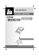
INTRODUCTION Your Pedestal CDG Karaoke System will provide you with fun and entertainment. It can let you be the “star” as you sing along with your favorite recordings and hear your voice with the music through the system’s speaker. This karaoke center is compact and designed to include many features, yet it is easy to use. After just a few simple instructions, you will become an expert.
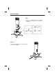
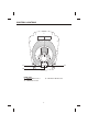
INSTALLATION STEP 1 1. Join the speaker (middle) into the stand (bottom) according to the installation illustration. 1 2 STEP 2 2. Tighten a self tapping screw at the bottom of the speaker (middle).
INSTALLATION STEP 3 3. Join the control panel (top) into the speaker (middle) according to the installation illustration. 2 1 A A B A B B Following the labels (A to A & B to B) to plug the connectors. STEP 4 4. Tighten a self tapping screw at the control panel (top).
CONTROL LOCATIONS See control locations as indicated on the next few pages.
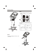
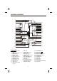
CONTROL LOCATIONS 1 2 3 20 21 22 23 24 25 26 27 28 29 30 4 5 6 7 8 9 10 11 31 12 32 13 33 14 15 34 16 35 17 36 18 19 FRONT VIEW 1. Camera Lens Open Button 2. Adjustable Camera Lens 3. ON/OFF Button 4. ON/OFF LED 5. Monitor Selector 6. Video Out Selector 7. BAND Selector 8. PROGRAM LED 9. Function Selector 10. REPEAT LED 11. Dial Pointer 12. MASTER VOLUME Control 13. 14. 15. 16. 17. 18. 19. 20. 21. 22. 23. 24.
CONTROL LOCATIONS 37 39 38 REAR VIEW 37. BRIGHTNESS Control 38. CONTRAST Control 39.
CONTROL LOCATIONS 44 40 41 42 43 45 46 47 SIDE VIEW 40. VIDEO IN Jack 41. AUX INPUT Jack (R) 42. AUX OUTPUT Jack (L) 43. AC Power Cord Jack 44. 45. 46. 47.
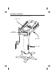
CONTROL LOCATIONS 51 48 49 52 50 WIRELESS MICROPHONE 48. ON Position 49. OFF Position 50. Battery Compartment 51. LED Indicator 52.
MAKING THE CONNECTIONS CONNECTING POWER You can power the system from a standard AC outlet by using the supplied power cord. CAUTION: The supplied AC power cord has a polarized plug that fits into the wall outlet only one way. If the plug does not fit properly, turn it over and try again. Do not force it. CONNECTING TO YOUR HEADPHONE A headphone jack is provided for using headphones instead of the built-in speaker. (Headphones are sold separately.
MAKING THE CONNECTIONS If your television or VCR does not have the required Video Input, you will need an RF Modulator (Radio Frequency Modulator), which connects through your TV Antenna or cable line and serves as Video Input. An RF Modulator can be purchased at almost any consumer electronics retailer. If you are connecting the video from the Singing Machine to either a television or a VCR video input jack, you must specify the source the TV or VCR is to display.
MAKING THE CONNECTIONS CONNECTING A VIDEO COMPONENT FOR INPUT Please follow the steps below to display CDG lyrics on the Singing Machine’s monitor from another video source: (1) Locate the multicolored patch cords. (2) Connect video cable (yellow) to the Video In of the side of the Singing Machine. (3) Connect the other end of the video cable (yellow) to the Video Output on another video source such as a VCR. (4) Set the Function Selector to AUX mode and the Monitor Selector to AUX.
MAKING THE CONNECTIONS CONNECTING AN AUDIO COMPONENT FOR INPUT To connect another audio source (such as a Tuner, an AV Receiver or a VCR) so you can sing along with its music, simply connect the Audio Output jacks (Red & White RCA jacks) to the Singing Machine’s AUX IN L & R jacks.
CD OR CD+G OPERATION D Warning - Tapping or dropping the microphone while it is on can permanently damage your microphone. Resist the urge to swing the microphone around by the cord! PREPARATION ! This unit is designed to play CD’s bearing the identification logo " ". If CD’s do not conform to the CD standard, they may not play properly. ! Fingerprints and dust should be carefully wiped off with a soft cloth. Wipe in a straight motion from the center of the disc to the outside edge.
CD OR CD+G OPERATION PLAY/PAUSE MODE ! To start playing, press the PLAY/PAUSE button. The first track [ ] and the PLAY/PAUSE LED will be lit. ! To temporarily stop playing, press the PLAY/PAUSE button. The PLAY/PAUSE LED Indicator will flash. ! To resume play, press this button again. PLEASE NOTE: Pressing pause when a CDG is playing may cause distorted lyrics on the monitor.
RADIO AND OTHER OPERATIONS AM/FM RADIO 1. Press the ON/OFF button. 2. Switch Function Selector to RADIO position. 3. Switch Band Selector to either AM or FM radio position. 4. Turn tuning knob to select desired station as indicated on dial. 5. Adjust Master Volume to your pleasure. 6. To turn the radio off, set Function Selector to CDG or AUX position. SING ALONG - RADIO 1. Follow operating instructions for AM/FM radio. 2. Connect the supplied Microphone to either one of the Mic input jacks. 3.
WIRELESS MICROPHONE INFORMATION Warning: Modifying, tampering and adjustment to this unit or replacement of any transmitter component (crystal, semiconductor, etc.) to this unit that could result in a violation of the rules. FCC NOTICE This wireless microphone system complies with Part 90 of FCC Rules. There is one frequency available for the system. You must get a licence for the frequency you plan to use before you use the system. Please look for this website http://wireless.fcc.
CARE AND MAINTENANCE POWER SWITCH After using the unit, turn off the power by pressing the ON/OFF button. CLEANING DISC Cleaning will not normally be necessary. However, should fingerprints, dust or dirt appear, you can wipe them off with a soft, lint-free cloth. Wipe the disc in a straight line from center to edge. You can moisten the disc first with ordinary tap water if necessary.
TROUBLE SHOOTING GUIDE If you have followed the instructions and are having difficulty operating the unit, locate the PROBLEM in the left column below. Check the corresponding POSSIBLE CAUSE column to locate and remedy the problem. PROBLEM POSSIBLE CAUSE SOLUTION No power when POWER is on. No power when plugged in. No power plug connection at the AC outlet. The AC outlet may not have power. Volume control is set to minimum. The wrong function is selected.
TROUBLE SHOOTING GUIDE PROBLEM No song lyrics appear on TV screen. POSSIBLE CAUSE Connect the video cable to the Video cable is not connected Singing Machine’s VIDEO OUT properly to the TV. and to the TV VIDEO IN. Using your TV remote to select VIDEO input or select the proper Source selector on TV is not VIDEO input on the TV itself. set to VIDEO.
SPECIFICATIONS AUDIO SECTION: OUTPUT POWER (MAXIMUM) OUTPUT IMPEDANCE 7 WATTS (RMS) 6 OHMS CD PLAYER SECTION: FREQUENCY RESPONSE SIGNAL - TO - NOISE RATIO WOW AND FLUTTER D - A CONVERSION NUMBER OF PROGRAMS SAMPLING SYSTEM 100 Hz - 20 kHz (+/-3 dB) 50 dB (A-WTD) IMMEASURABLE 1-BIT DAC 20 STEPS RANDOM ACCESS PROGRAMMING 8 TIMES OVER SAMPLING MONITOR SECTION RADIO SECTION: AM FREQUENCY RANGE FM FREQUENCY RANGE 7” BLACK AND WHITE TV MONITOR NTSC SYSTEM 220 LINE RESOLUTION 530-1710 kHz 88-108 MHz MICROP
THE SINGING MACHINE KARAOKE GLOSSARY OF TERMS In addition to all of the terminology associated with consumer electronics products, a few additional terms are used almost exclusively in karaoke. These terms are meant to familiarize you with the world of Karaoke. The features listed below may not necessarily pertain to the particular model Singing Machine that you have.
The Singing Machine Company, Inc. 6601 Lyons Road, Bldg. A7, Coconut Creek, FL33073-9902, USA. TEL: (954) 596-1000 FAX: (954) 596-2000 988-0411-ENG01 PRINTED IN CHINA VISIT OUR WEBSITE www.singingmachine.