2 1. Contents 1. Contents 2. Safety instructions 3 3. Assembly, putting into operation, connection 4 4. Control elements 5 5. Display 6 6. General 7 7. Factory setting 7.1 Changing the settings 10 7.2 Selecting the operating mode 11 7.2.1 AU = Automatic switchover Page 8 11 7.2.2 cHA = Weekday-related switchover 12 7.2.3 no 13 = No switchover 8. Switching commands 14 9. Date 16 9.1 Single date without/with year 17 9.2 Date range without/with year 18 10.
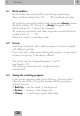
. Safety information Installation must be carried out and inspected by a specialist or under his supervision. For assembly: • Suitable for use in ambient conditions with normal contamination levels • Use the appropriate Grässlin accessories for wall surface-mounting. If correctly installed in accordance with VDE 0100, Part 40, the parts with which contact is still possible can be regarded as double-insulated (protection class II).
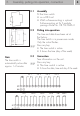
. Assembly, putting into operation, connection Note: The time switch is automatically active after approx. 1–2 minutes 4 3.1 Assembly Fit the time switch • on a DIN rail • Wall surface-mounting is optional Surface-mounting set for 6 modular spacings Article No. 03.59.0046.2 3.2 Putting into operation The time and date have been set at the factory. The time switch is in power-save mode. Only the colon flashes. Press any key: • The time switch is active • It shows the time (day of the week) 3.
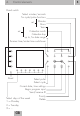
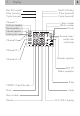
. Control elements Hand switch Select minutes/seconds for cycle/pulse functions Minutes set Hours Years Calendar month set Calendar day up to, for date range Summer time/winter time switchover Reset Select pulse Select cycle Current date, time settings Begin program input Send/receive IR Priority Select days of the week Delete 1 = Monday 2 = Tuesday 3=… GB 5
. 6 Display Day (US month) Pulse (minutes) Cycle (minutes) Month (US day) Pulse (seconds) Cycle (seconds) Channel 1 Continuous operation Manual operation Automatic operation Switching state Year number Block number Priority Channel 2 Summer time/ winter time switchover Channel 3 Channel 4 Automatic operation DCF 77 Radio reception Pulse 1234567 = Day of the week Hours Cycle Year number Minute 12 h/24 h display
. General 6.1 Block numbers Block numbers are automatically issued during programming. There are block numbers from 00 ....... 99 (note block principle). 7 All switching commands without date assignment always receive the block number 00. (Priority 0 is always assigned to the block number 00 – it cannot be changed). All switching commands with date assignment receive the block numbers from 01 ..... 99. These are issued in ascending order. 6.
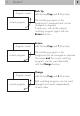
6. 8 General Program saved current program Program saved current program Program saved current program Back Up with the key Prog and 1 (Day key) The switching program in the foreground is preserved and can be changed as required. If necessary, call up the original switching program again with the Restore function. Restore with the key Prog and 7 (Day key) The switching program in the foreground can be changed as required.
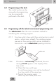
9 6. General 6.4 Programming at the desk The control section can be removed and programming can be conveniently performed at the desk. 6.5 Programming with the talento taxxi (manual programming unit) The talento taxxi offers the most convenient method for transferring the switching programs. 6.5.1 From time switch to time switch (from control section to control section – without mains voltage!).
6. 10 General 6.5.2 Compile your switching programs on a PC with the software talento dialog. They are then transferred to the taxxi via the PC interface. With the taxxi, the switching programs are now transferred to the relevant time switch (control section) via the infrared interface. Refer to the talento dialog manual. talento taxxi Note: Software and accessories can be ordered separately: • talento taxxi set Art.No.: 07.01.0029.
6. General 6.6 Service 6.6.1 Error messages The time switch signals malfunctions: • Er 04 – in the event of incorrect access to the EEProm. This error message can appear in individual cases. Press any key and the time switch will continue to run normally. If this error message appears often, we recommend that the time switch be replaced. Consult your dealer. • Er 02 – in the event of incorrect transfer via the IR interface. Transfer the program again. There may be read/write errors.
7. 12 Factory setting The default values correspond to Central European Time (CET). The time switch offers 3 operating modes. The date and time and the operating mode AU are set. Operating modes: • AU Automatic switchover of the summer time control function, see Section 7.2.1 The switchover takes place on the legally defined date. • cHA Weekday-related switchover of the summer time control function, see Section 7.2.2 You enter the summer time end date valid for your location/ country. e. g.
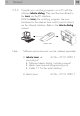
7. 13 Factory settings Change round date display (USA/GB method) Press the key 1x. The colon does not flash. Press the 2-key (day of the week) 1x. (Month, day) Press the key 1x. The input is ended. Adjusting to CET If the time switch receives the time signal DCF 77, it may be necessary – depending on the location – for the display to be adjusted. You have the possibility of adjusting the time by up to +/- 2 hours with respect to the DCF 77. Press the key 1x. The colon does not flash.
14 7.1. Changing the settings Note With all settings/changes which you make, it is possible to abort or complete the entry/change at any time with the key. Date and time Press the key 1x. The colon does not flash. Setting and changing the date: With the Day key – calendar day With the Month key – calendar month With the Year key – calendar year Setting and changing the time: With the h key – hours With the m key – minutes Press the key 1x. The input is completed. The display shows the date and time.
15 7.2 Selecting the operating mode 7.2.1 AU 7.2.2 cHA 7.2.3 no = Automatic switchover = Weekday-related switchover = No switchover 7.2.1 AU = Automatic switchover This data can only be read at this point. See Section 7.1 to change data. Press the key 1x. The colon does not flash. Press the + 1h key 1x. Start of summer time, e. g. 28.03 in the year 1999 and AU are displayed. Press the key 1x., flashes. End of summer time e. g. 31.10 in the year 1999 and AU are displayed. Press the key 1x.
16 7.2 Selecting the operating mode 7.2.2 cHA = Weekday-related switchover Press the key 1x. The colon does not flash. + 1h key once or twice until cHA appears Individual summer time start setting: Calendar day with the Day key Calendar month with the Month key Press the key 1x, flashes. Individual summer time end setting: Calendar day with the Day key Calendar month with the Month key Press the key 1x. The input is completed. The identifier + 1h automatically appears for operating mode cHA.
17 7.2.3 no = No summer time switchover Press the key 1x. The colon does not flash. Press the+ 1h key as often as necessary until no appears. The time switch operates with the calendar, but without automatic switchover. The manual switchover function can always be activated with the key + 1h. Press the key 1x. The input is completed. The display shows the date and the time.
8. 18 Switching commands The input of the switching commands applies to all types of assignment • Switching commands without date assignment, always in block 00, always with priority 0 (standard switching commands). • Switching commands with single date, see Section 9.1 • Switching commands with date range, see Section 9.2 • Pulse switching commands, see Section 11 • Cycle switching commands, see Section 12 You determine the switching times and the switching state for the relevat channel.
19 Setting the days of the week: 1 2 3 4 5 6 7 (Monday … Sunday) Setting the switching state: With the 1/0 key for each channel, separately select = ON; = OFF Briefly press the Prog. key 1x. The switching command is saved. A free memory location is displayed – for additional inputs. or Press the key 1x. The input is completed. The display shows the date and the time.
9. • • • 20 Entering the date Switching commands to which a date is assigned are arranged in blocks. Priority 2 is assigned at the same time. Change priority – see Section 10 The block number is assigned automatically (01 to 99) (switching commands without date assignment always in block 00, always with priority 0), see Section 10 Several entries to which particular switching times are assigned can be in one block.
9.1 Single date without/with year 21 Press the Day, Month or Year key 1x. The current date, a new block number and the priority 2 are always offered. Enter the enquired date: (without or with year) Calendar day with the Day key Calendar month with the Month key Calendar year with the Year key Change priority, see Section 10 Press the Prog. key only briefly. This input is saved. A free memory location is displayed – for additional inputs.
22 9.2 Date ranges without/with year Press the Day, Month or Year key 1x. The current date, a new block number and priority 1 are always offered. Enter the enquired starting date: (without or with year) Calendar day with the Day key Calendar month with the Month key Calendar year with the Year key Change priority, see Section 10 Press the key 1x. flashes.
23 A free memory location is displayed for further entries. Have you made all date entries for this block ? If so, enter the relevant switching commands, see section 8 or Press the key 1 x. The input is completed The display shows the date and time.
24 10. Priority Switching commands with the data assignment can be occupied with different priorities (block number 00 and priority 0 is defined for switching commands without date assignment). If you start with a date during programming, a new block number and priority 2 are always offered = default for a single date. If a date range is entered – with the key –, priority 1 is automatically assigned. The priority can be changed between 1 and 9.
25 11. Pulse switching commands If a load with a higher switching frequency – in the seconds range – is switched ON and OFF, it must be ensured that adverse effects on the quality of lighting units (flicker) and faults in radio and television reception are avoieded You determine the times for pulse switching commands, symbol . Pulse times are: 01...99 seconds or 01...99 minutes. A pulse switching command consists of: Start time and ON or OFF switching duration.
26 Preselection for seconds or minutes m/s key Press the key step-wise. Set the pulse time from 01 ... 99. Note: If the key is pressed for longer, adjustment takes place in steps of 05. Press the Prog. key 1x only briefly. The switching command is saved. A free memory location is displayed – for additional inputs. or Press the key 1x. The input is completed The display shows the date and the time.
12. Cycle switching commands 27 If a load with a high switching frequency – in the seconds range – is switched ON and OFF, it must be ensured that adverse effects on the quality of lighting units (flicker) and faults in radio and television reception are avoieded You determine the times for cyclical switching commands. Symbols: = cycle duration (2...99 sec. or 1...99 min.) = ON switching duration (1...99 sec. or 1...99 min.
28 12. Cycle switching commands Start time ON switching duration 10 minutes Pause Cycle duration 60 min. End time Pause Cycle duration 60 min. Select free memory location: Press the Prog. key 1x. – –.– – –– –– Enter as required: – Switching command, weekday(s), switching state, see Section 8 – Single date without/with year, see Section 9.1 – Date range without/with year, see Section 9.2 Press the key 1x. 01 minutes are offered.
29 Setting the cycle time from 01 ... 99 Press the key step-wise Note: If the key is pressed for longer, adjustment takes place in increments of 05. Setting the ON switching duration, 01 ... 99 This can never be greater than the previsously set cycle time. Press the key step-wise. Press the Prog. key 1x only briefly. The switching command is saved. A free memory location is displayed – for additional inputs. or Press the key 1x. The input is completed. The display shows the date and the time.
13. Read – Change – Delete – Reset • • • • You You You You 30 read the number of free memory locations/block numbers read the program contents in steps change, overwrite the program contents delete the program contents 13.1 Read Select free memory location: Press the Prog. key 1x. – –.– – –– –– Press the Prog. key only briefly. The number of free block numbers and the number of free memory locations are displayed. Press the Prog. key again only briefly.
31 Read contents of block 01 to 99: Press the Prog. key 1x for approximately 1 second. Your are in block 01. Read the contents of this block: Press the Prog. key only briefly step-wise. The contents are displayed in turn. If a date range is displayed, „date “ appears in the display. With the symbol key, read the end date and switch back to the start date. If a cycle switching command is displayed, appears in the display. Press the key 1x and read the ON or OFF switching duration. Again press the Prog.
13. Read – Change – Delete – Reset 13.2 Change Every program contents can be changed/overwritten individually. With the Prog. key (read), call up the contents which you want to change/overwrite. Changing is performed in the same way as entering new data (see the relevant Section). • • • • • Switching commands, see Section 8 Date, see Section 9 – Single date without/with year, see Section 9.1 – Date range without/with year, see Section 9.
33 13.4 Delete – all switching commands Press the Prog. key 2x. The number of free block numbers and the number of free memory locations is displayed. Press the Clear key 1x. c l also appears in the display and flashes. Press the Clear key 1x. All contents are deleted. The display shows the block number 0 and the number of the max. memory locations. 13.5 Reset Important! No metallic pointed objects (e. g. needles) may be used for keys which are pressed with a tool.
34 14. Manual switch You change – manually – the current switching state. However, the individually set switching program is preserved. 1 for channel 1 2 for channel 2 3 for channel 3 4 for channel 4 = Automatic = OFF = ON The switching state corresponds to the entered program. = Manual mode = ON = OFF You change – m a n u a l l y – the current switching state. The next switching command in the program is executed again automatically.
35 16. Technical data 1, 2, 3 and 4-channel year clock Dimensions (H x W x D) mm Distributor cut-out mm Weight g (approx.