
Instructions


16 17
Elements
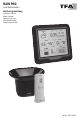
Wireless weather station (base station)
Display (Fig.1)
FORECAST display (Fig.1-A)
Fig.1-A1 Weather symbols
Fig.2-A2 Trend indicator
TIME & DATE display (Fig.1-B)
Fig.1-B1 Time
Fig.1-B2 DCF symbol
Fig.1-B3 Battery symbol base station
Fig.1-B4 Weekday and date
RAIN display (Fig.1-D)
Fig.1-D1 Reception symbol
rain sensor
Fig.1-D2 Rainfall interval and
alert symbol
Fig.1-D3 Rainfall amount of the last
hour, the last 24 hours,
7 days, current month,
year and the total amount
of rainfall, history of the
last 12 individual months
Fig.1-D4 Battery symbol
rain sensor
Fig.1-D5 Today rainfall amount
Fig.1-D6 Today rainfall graph
Fig.1-D7 Animated rain symbol
(when it is raining)
INDOOR display (Fig.1-E)
Fig.1-E1 Indoor humidity
Fig.1-E2 Indoor temperature
Fig.1-E3 Trend arrows
Fig.1-E4 Alert symbol HI/LO
OUTDOOR display (Fig.1-C)
Fig.1-C1 Symbol for alternating
channels
Fig.1-C2 Channel number
Fig.1-C3 Reception symbol
temperature-humidity sensor
Fig.1-C4 Battery symbol
temperature-humidity sensor
Fig.1-C5 Alert symbol HI/LO
Fig.1-C6 Outdoor humidity
Fig.1-C7 Trend arrows
Fig.1-C8 Outdoor temperature
Buttons (Fig.2) Housing (Fig.2)
Fig.2-A ALERTS button
Fig.2-B TEMP button
Fig.2-C RAIN button
Fig.2-D + button
Fig.2-E - button
Fig.2-F SET button
Fig.2-G CHANNEL button
Fig.2-H Wall mounting holes
Fig.2-J Stand (fold out)
Fig.2-K Battery compartment
Temperature-humidity sensor (Fig.3) Rain sensor (Fig.4)
Display Buttons & housing Housing
Fig.3-A Channel 1,2,3
Fig.3-B Transmission signal
Fig.3-C Temperature
Fig.3-D Humidity
Fig.3-E Battery symbol
Fig.3-F TX button
Fig.3-G 1 2 3 switch for
channel selection
Fig.3-H Battery compartment
Fig.3-J Support for wall mounting
or table standing
Fig.4-A Funnel
Fig.4-B Locking tabs
Fig.4-C Base
Fig.4-D Battery compartment
Fig.4-E Rocker
Fig.4-F 4 screw holes
for mounting
Getting started
Insert the batteries
y Place the base station and all transmitter on a table at a distance of about 1.5 meters from each other.
Avoid being close to possible sources of interference such as electronic devices and radio equipment.
Temperature-humidity sensor
y Open the battery compartment of the temperature-humidity sensor (Fig.3-H) and insert two new AA 1.5 V
batteries, polarity as illustrated. All LCD segments will be displayed for a short moment.
y The transmitter’s display shows the current temperature and humidity (Fig.3-C+D).
The switch is set to channel 1 (Fig.3-G).
y Close the battery compartment.
Rain sensor
y Open the two tabs on each side (Fig.4-B) of the rain sensor and lift the funnel portion(Fig.4-A)
off the base (Fig.4-C).
y Open the battery compartment (Fig.4-D) and insert two new AA 1,5 V batteries. Make sure the polarities are
correct (see marking on the cover).
y Close the battery compartment.
y Remove the transport lock of the rocker (Fig.4-E).
y Close the housing cover and lock it.
Base station
y Remove the protective lm from the display.
y Insert three new batteries 1,5 V AA into the battery compartment (Fig.2-K) of the base station.
Make sure the polarities are correct.
y The device will alert you with a beep and all LCD segments will be displayed for a short moment.
y The indoor temperature and humidity (Fig.1-E1+E2) humidity appear on the display.
Outdoor values reception
y After the batteries are inserted, the outdoor values of the outdoor sensors will be transmitted to the base station.
y The base station will scan the outdoor values of the transmitters. The reception symbols of the
temperature-humidity sensor (Fig.1-C3) and the rain sensor (Fig.1-D1) are ashing.
y If reception is successful, beeps sound and the outdoor values are permanently displayed (Fig.1-C6+C8).
y The rainfall amount (initially 0.0 mm) (Fig.1-D5) is displayed. To simulate values, move the rocker (Fig.4-E)
(transmission time rain sensor: 90 seconds).
y If the reception of the outdoor values fails within three minutes, “- -“ appears on the display. Check the
batteries and try it again. Check if there is any source of interference.
y You can also start the outdoor transmitters search manually later (e.g. if the transmitter is lost or if the
batteries are changed).
y Press and hold the CHANNEL button (Fig.2-G) for three seconds to search for the temperature-humidity
sensor. Press the TX button (Fig.3-F) in the transmitter’s battery compartment (Fig.3-H).
y Press and hold the RAIN button (Fig.2-C) for three seconds to search for the rain sensor.
y A beep will sound. The reception symbol of the transmitter ashes and the base station will scan the
outdoor values.