
Computer Hardware User Manual

PCI200 User Guide Texas Memory Systems, Inc. (8/6/01) C-1
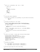
Appendix C – XP-15 Hardware Control and Status Registers
The XP-15 is a custom hardware adapter designed to provide processing power to a host computer (DEC
Alpha, Intel PC, etc..). The XP-15's data bus is 32-bits or 64-bits wide (depending on the host PCI slot).
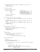
The following tables describe the XP-15's hardware control registers. Each register is classified as read only,
write only, or read/write. The least significant bit of each register is always tied to the least significant bit of
the PCI bus. Any unspecified bits should be masked in software after they are read, even though they will
not be used.
As defined by the PCI Local Bus Specification Rev. 2.2, the XP-15 has one Base Address Regions. All
registers are defined as offsets into this one address region. Bit-level definitions of all registers, including
rules for their use, appear in the following tables and paragraphs.
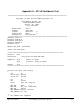
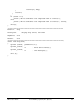
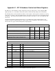
XP-15 Hardware Registers
Register Name Base
Address
Region
Offset Type Size
Control-Status Register (CSR) 0 0h R/W 32 bits
Low PCI SN command address register[31..0] 0 4h R/W 32 bits
High PCI SN command address register[63..32] 0 8h R/W 32 bits
Low PCI SN response address register[31..0] 0 Ch R/W 32 bits
High PCI SN response address register[63..32] 0 10h R/W 32 bits
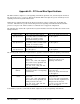
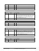
Control-Status Register (32 bits, R/W)
Bit # Name Type Description
31-16 RESERVED N/A These bits are reserved.
15 Reset WO Softreset, puts the XP-15 in the power-up state.
14 Start WO Informs XP-15 to start processing SN command.
13 END WO Indicates host is big Endian.
12-10 RESERVED N/A These bits are reserved.
9 64 WO Indicates XP-15 is in a 64-bit PCI slot
8 RESERVED N/A This bit is reserved.
7 DMADONE RO Indicates the DMA is finished.
6 STOP RO Indicates the STOP bit has been encountered.
5 PAUSE RO Indicates the XP-15 is paused.
4 ERR RO Indicates the XP-15 has received an SN checksum error.