TEXAS MEMORY SYSTEMS, INC. RamSan-300/320 User’s Manual Version 1.
Any trademarks or registered trademarks used in this document belong to the companies that own them. Copyright © 2004, Texas Memory Systems, Inc. All rights are reserved. No part of this work may be reproduced or used in any form or by any means - graphic, electronic, or mechanical, including photocopying, recording, taping, or information storage and retrieval systems - without permission of the copyright owner.
Table of Contents Preface ......................................................................................................... 1 Document Overview .................................................................................... 1 Conventions............................................................................................... 1 Safety Precautions ...................................................................................... 1 Revision History .......................................
8.3 Batteries.........................................................................................77 8.4 Fans ..............................................................................................77 Chapter 9 – Troubleshooting .........................................................................78 9.1 System Event Log ............................................................................78 9.2 Support Log .................................................................................
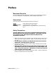
Preface Document Overview This document provides operating procedures for the RamSan-300/320. It covers installation, management, and troubleshooting issues. Conventions This document uses the following textual conventions: Select Ethernet Setup lunconfig Front panel button descriptions Front panel text (menu items) Management port (serial/Telnet) commands and text. Safety Precautions PLEASE OBSERVE ALL DUE SAFETY MEASURES WHEN WORKING WITH SENSITIVE ELECTRICAL EQUIPMENT.
Revision History The following table describes revisions to this document: Version 1.0 1.1 1.2 1.3 1.4 1.5 1.6 Comments Initial release Added component photographs Added information about using the help function in the text management interface. Added Appendix A. Updated power supply details.
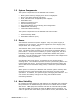
Chapter 1 1.1 – Introduction Overview The RamSan-3xx series solid-state disk uses SDRAM (memory) as its primary storage. This technology enables practically instantaneous data access, which results in dramatic application performance increases. Texas Memory Systems (TMS) designed the RamSan to be highly available and fault tolerant. The system has higher availability than RAID or JBOD systems because the primary storage media is SDRAM, which does not require moving parts.
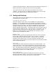
1.2 System Components The system components for the RamSan-300 include: • • • • • • • • • Main system memory ranging from 16 to 64 Gigabytes One to four Fibre Channel controllers Dual, redundant hot-swappable power supplies Redundant fans Ethernet monitoring port Serial monitoring port Front panel display for monitoring and configuration SNMP based monitoring Java-based Web monitoring The system components for the RamSan-320 also include: • • 1.
contains redundant batteries. When fully functional and fully charged, the batteries are able to provide at least 30 minutes of operation. The system monitors the internal disks and batteries for a failure condition. In such an event, it notifies the operator of an error through the front panel display and the management software. 1.5 Configurable Backup The RamSan-320 allows the administrator to set backup modes for each LUN individually or system wide.
1.6 Performance The RamSan-3xx series solid state disk is the ultimate in performance storage. With up to eight Fibre Channel ports in a 3U package, the RamSan-3xx series delivers unparalleled bandwidth and I/O. The RamSan-3xx series is capable of 250,000 IOPS (I/O operations per second) and 3,000 MB/sec of read or write performance.
Chapter 2 – Installation 2.1 Electro-Static Discharge Warning Important: Please take full E.S.D. precautions if it is necessary at any time to come into contact with any circuit boards, components or connectors. Electrostatic discharge can damage the components used in the RamSan and its interfaces. 2.2 Battery Warning The internal batteries in the RamSan-320 are charged with enough voltage to power a fully loaded system for approximately 30 minutes.
RamSan-300/320 User’s Manual Management Port Memory Board 12 Fibre Channel Port 1 Memory Board 4 Fibre Channel Port 2 Memory Board 8 Fibre Channel Port 3 Memory Board 0 Fibre Channel Port 4 Power Supplies 2.5v Power Memory Board 1 Memory Board 5 Memory Board 9 Memory Board 13 Memory Board 2 Memory Board 6 Memory Board 10 Memory Board 14 Memory Board 3 Memory Board 7 Memory Board 11 Memory Board 15 3.
2.4 Rack Mounting The RamSan-3xx series solid state disk is a 3U rack-mountable system. TMS ships the system with the slides and equipment needed to install it into a standard 19” rack. 2.5 Connecting the Fibre Channel Ports After you have inspected the system and properly mounted it, connect the Fibre Channel ports on the RamSan to either your server or to a Fibre Channel switch.
“Power” AC Voltage Figure 2-3 RamSan Power Supply The power supply includes the following button and indicators: “Power” switch The large black button above the power supplies acts as an on/off switch and will silence the warning buzzer. • The button provides a means to activate the power supplies (turn them on) after a system shutdown. If the system shuts down for any reason other than a power failure, press the “Power” switch to turn the system back on.
AC Voltage indicator light When the power supply is connected to AC power and is operating properly, the indicator light attached to each power supply is green. If the green light is not on, either the power supply is disconnected from an AC power source or the power supply has failed. Check the power cable to determine if power has been lost to the supply or whether the supply has failed.
2. In a RamSan-320, the front panel displays “Restoring Data” and cycles between a progress bar and an estimated time until completion. Administrators may use this to determine how much time before the system is on-line. This information is also available through the Text Management Interface. This process will take approximately one minute for every four Gigabytes of system memory. Restoring Data ... 73.8% Restoring Data ... Est. Time Left 73.
Chapter 3 – Management Tool Overview 3.1 Front Panel Display The Front Panel Display provides a quick and easy way view the RamSan’s status. It displays the current progress of disk synchronization and shows system warnings and failures.
↓ The “↓” button scrolls down through the menu. The “↓” button is also used confirm certain commands, as indicated on the display. If the menu is not selected, this button is disabled. 3.1.
To connect to the serial port, use the DB-9 non-null serial cable supplied with the system. 3.2.2 Connecting using Telnet Once the administrator configures the Ethernet port on the RamSan using either the front panel or the serial port, you may remotely monitor the system using a Telnet session. Set your terminal settings to VT100 mode. In order to use the Ethernet port, first configure the IP address for the RamSan by using the front panel display or from the serial port.
When the user selects some menu items, the program displays sub-menus, as shown in Figure 3-3: Text Management Interface Sub-Menu: Figure 3-3: Text Management Interface Sub-Menu When in a sub-menu, the user can select “C” to cancel or press the “ESC” key to return to the menu. Once satisfied with the changes made on a menu, the user must select “S” to save all of the changes. Pressing “ESC” or selecting “Q” disregards any changes and returns to the previous menu.
On status screens, the program provides the user with several options: • • • • Press ‘Q’ to exit the menu Press ‘I’ or ‘D’ to increment or decrement the interval between statistics updates in ¼ second intervals Enter ‘R’ to immediately refresh the data on the screen Enter [SPACE] to view additional information To exit the Text management interface, enter ‘Q’ from the Main Menu. Figure 3-5: Scrolling Sub-Menus Some of the sub-menus have a large numbers of items and therefore scroll.
3.3.1 General interface layout and instructions Texas Memory Systems designed the web management interface as a metaphor for the actual system components. For detailed information, the user simply clicks on the component. Clicking on the management port also displays additional information about the system’s actions. Some of the components have multiple ‘tabs’ of information. The web interface outlines all failed components in red and all components with warnings in yellow.
Chapter 4 – Administration Functions 4.1 Security The RamSan has several features that allow the administrator to control system access, including password protected access and the ability to disable remote access via Telnet, Web, or SNMP. 4.1.1 Logging into the system The RamSan has one account: “admin.” 4.1.2 Set password Since it is possible to remotely access the RamSan through the management port, TMS includes a password feature for system security.
Via Web Interface To • • • • • • change the administrator password via the web interface: Click on the “Management Control Processor” graphic Click the “General Config” tab Enter your old password; The system requires your old password for security reasons Enter your new password Confirm the new password Click the “Change” button The system immediately changes the administrator password.
Via Text Management To change the administrator password via Text Management Interface: • From the Telnet Main Menu, select “Management setup” • Select “Change password” • Enter the admin password and press [ENTER] If you are not logged in through the console, you must verify your password. For security reasons, the system does not display the typed letters when typing in passwords. Figure 4-2: Password Change 4.1.
Via Web Management To enable/disable Telnet via the web interface: • Click on the “Management Control Processor” graphic • Click on the “Network” tab To enable Telnet, check the “Allow Telnet” checkbox and press the “Save” button. To disable Telnet, uncheck the “Allow Telnet” checkbox and press the “Save” button.
Via Text Management • • • • From the Telnet Main Menu, select “Management setup” Select “Enable/Disable Telnet.” If Telnet is currently enabled, your option will be “Disable Telnet” and visa versa. Press the “ ” key or [ENTER] to toggle between the sections Select “Save changes and exit” to save the changes. The menu displays the current Telnet status above the menu options, as shown in Figure 4-4: Telnet Setup. Users currently connected through Telnet remain connected until their session ends.
4.1.4 Enable/disable Web Interface The system allows the administrator to disable Web access to prevent users from accessing the system through the Web interface. Via Web Management To disable the web interface via the web interface: • Click on the “Management Control Processor” graphic • Click on the “Network” tab To disable the web interface, uncheck the “Allow Web” checkbox and press the “Save” button.
4.2 Configuring Ethernet settings The RamSan allows system monitoring and configuration through the serial port and the Ethernet port. To access the system’s Ethernet port, the administrator must assign the RamSan an IP address, subnet mask, and possibly a gateway. The administrator may assign the IP address in one of three ways: Static IP, DHCP, or No Ethernet. The default factory setting is DHCP. For any questions regarding IP assignment values, please consult your network administrator. 4.2.
• Enables you to set a static IP address for the RamSan. • Sets the IP configuration to DHCP • Disables Ethernet • Returns to the Main Menu without making any changes Static DHCP None No change Talk to your network administrator for the proper IP assignment type. The default factory setting is DHCP. Use the “Select” button to select the desired method of IP assignment. If you did not choose “Static IP” you are asked to confirm the selection with the “↓” button.
After you have finished entering the IP, the top line of the front panel changes to “Subnet Mask.” Using the same procedure as entering the IP address, enter the subnet mask. The final value you must enter is the “Gateway Address.” If the RamSan is on a private network and this value is not needed, enter the value “0.0.0.0” to tell the RamSan to ignore this entry. Subnet Mask _ Gateway Address _ After entering all three values, the display prompts you to confirm the command with the “↓” button.
4.2.2 Configuring Ethernet settings via Text Management Interface • • From the Telnet Main Menu, select “Management setup” Select “Configure Ethernet” Figure 4-5: Ethernet Setup The system displays the “Ethernet Setup” screen, as shown in Figure 4-5: Ethernet Setup.
To • • • set the hostname: Select “Select hostname” Enter the hostname and press [ENTER] When all Ethernet setup is complete, select “Save changes, restart the network, and Exit” 4.3 Power Down Settings The RamSan has features that allow the administrator to safely power down the system. 4.3.1 Manual shutdown The administrator can shut down the RamSan manually from the front panel and via Text Management Interface.
Now, the front panel display indicates that the system is powering off. Depending on the system mode and the size of memory, this procedure may take a while. The front panel cycles between a power off status bar and an estimated time until the system completes the power off. *** Powering Off *** Via Web Management To perform a manual shutdown via the web interface: • Click on the “Management Control Processor” graphic • Click on the “General Info” tab Press the “Shutdown” button.
Chapter 5 – Monitoring Functions 5.1 Viewing system health and status The RamSan makes it possible to view system health variables in a variety of ways. This allows you to easily determine that the system is in good health and, under rare circumstances, determine that a failure is imminent or has occurred. 5.1.1 Front panel monitoring When the menu on the front panel is not in use, the display monitors various aspects of the system.
Status The following status levels are possible: “GOOD” System Status: This is normal operation. “WARNING” Indicates that the RamSan has detected a system warning. Warning statements scroll across the front panel display. Possible warnings include: • Pwr supply # removed • AC lost at one or both power supplies • One or both batteries are low • Temperature warning • One disk removed “ERROR” Indicates that the RamSan has detected a system failure. Error statements scroll across the front panel display.
Fibre Channel Performance The front panel display can show the Fibre Channel Controller performance: From the front panel main Active Monitor Mode menu, select “Active Monitor Mode.” This mode shows the performance bars for each Fibre Channel port. The numbers represent the Fibre Channel Controllers. If a controller is not installed, the number and corresponding performance will not display. The top bars represent the port A and the bottom bars represent port B.
LED Performance Monitoring If your system is equipped with front panel LEDs, you can also view bandwidth and IOPS: From the front panel main menu, select “LED Display” This mode uses the LEDs to display bandwidth or IOPS. To use the LEDs to display bandwidth, select “Display Bandwidth.” To use the LEDs to display IOPS, select “Display IOPS.” LED Display Display Bandwidth Once you select one of the above options, the display will ask you to “Enable Autoblink.
5.1.2 Identifying a RamSan When you have more than one RamSan, the “Identify Device” feature helps you to physically locate which RamSan you are monitoring. This feature blinks the front panel display. The following demonstrates how make the front panel display start and stop blinking.
5.1.3 Viewing system uptime The system uptime provides information about how long the system has been powered on. Via Web Interface To view the system uptime via web interface: • Click on the “Management Control Processor” graphic • Click on the “General Info” tab The “General Info” screen displays the “Uptime” below “Firmware version.
Via Text Management To view the system uptime via Text Management Interface: • From the Telnet Main Menu, select “Health and Status” The system displays the current system uptime in days, hours, minutes and seconds at the top of the “Health and Status” screen, as shown in Figure 5-3: Health and Status: Figure 5-3: Health and Status RamSan-300/320 User’s Manual - 37 -
5.1.4 Viewing system health The system health allows the user to monitor vital system health statistics, such as general state information, voltages, temperatures, and fan speeds. Via Web Interface Information concerning the disks, batteries, power supplies, and fans are all found in separate locations through the Web interface. The RamSan-300 does not display the disks or battery graphics.
Batteries (Not displayed for the RamSan-300) • • Click on the “Batteries” graphic Click on the “General Info” tab Figure 5-5: Battery Status via Web interface RamSan-300/320 User’s Manual - 39 -
Management Control Processor To view the MCP status via web interface: • Click on the “Management Control Processor” graphic • Click on the “General Info” tab Figure 5-6: MCP General Info Tab for Status RamSan-300/320 User’s Manual - 40 -
Power supplies • • Click on the “Power Supply” graphic Click on the “General Info” tab Figure 5-7: Power Supply Status via Web Interface RamSan-300/320 User’s Manual - 41 -
Fans • • Click on the “Fans” graphic Click on the “General Info” tab Figure 5-8: Fans Status via Web interface RamSan-300/320 User’s Manual - 42 -
Via Text Management • • From the Telnet Main Menu, select “Health and Status” Select “View system monitor” Figure 5-9: Text Management Interface System Health Status The states are classified as “Good,” “Warn,” and “Error”: “Good” This states that everything is functioning under normal operating conditions. “Warn” This indicates a potential problem to look into, but the problem is not an immediate threat to system stability.
5.1.5 Viewing detailed fibre channel controller status Via Web Interface The Web interface allows you to view all of the fibre channel information, but one fibre channel controller at a time.
Via Text Management • • From the Telnet Main Menu, select “Health and Status” Select “View Controller Status” Figure 5-11: Fibre Channel Controller Status via Text Management Interface RamSan-300/320 User’s Manual - 45 -
5.2 Statistics The storage administrator can monitor important statistics that define the level of system performance through the various management utilities. These statistics include Input and Output operations per second (IOPS) and bandwidth. 5.2.
Via Text Management • • • From the Telnet Main Menu, select “Health and Status” Select “View Controller Statistics” Select “IO/sec summary” The “IO/sec Summary” screen, as shown in Figure 5-13: IO/sec Summary, shows the IO read (r), write (w), and totals (t) for each fibre channel controller in the system. It also displays a total across all of the FCs present.
5.2.2 Viewing bandwidth summary Via Web Interface To • • • view the bandwidth statistics via the web interface: Click on one of the “Fibre Channel” graphics Click on the “Statistics” tab Click the radio button next to “Bandwidth” The graphing tool provides the option to view read, write, and total bandwidth, as well as a running average of each of these statistics. To decode the colors on the graphical display, see the legend below the check boxes.
Via Text Management To • • • view the bandwidth summary via Text Management Interface: From the Telnet Main Menu, select “Health and Status” Select “View Controller Statistics” Select “Bandwidth summary” The “Bandwidth Summary” screen displays the bandwidth read (r), write (w), and totals (t) for each fibre channel controller in the system. It also displays a total across all of the fibre channel controllers present.
5.2.3 Viewing controller details Via Text Management To • • • view the controller details via Text Management Interface: From the Telnet Main Menu, select “Health and Status” Select “View Controller Statistics” Select “Controller details” The “FC Overview” screen shows a summary of IOPS and bandwidth for a particular controller. Figure 5-16: FC Overview Screen 5.3 Logs In the case of a system failure, the system stores detailed information about the failure in the system event log.
Via Text Management To view the system event log or support log via Text Management Interface: • From the Telnet Main Menu, select “Log Files” • Select “View System Log” or “Get Support Log” Figure 5-17: Error and System Event Log The system displays the commands for navigating the system event and error logs at the bottom of the window. 5.3.
Chapter 6 – LUN Configuration The extremely versatile RamSan-3xx series supports a variety of configurations and access control methods. LUN configuration is a memory-partitioning tool that allows the administrator to configure system memory into LUNs (Logical Unit Numbers) that may be assigned to specific Fibre Channel ports in the RamSan.
6.1 A example LUN configuration This section summarizes how to change the system memory configuration from the default factory configuration to a new configuration, which consists of four partitions and has access lists that allow only four host machines to use the RamSan. This demonstration assumes the four HBAs and the RamSan’s Fibre Channel ports are attached to the same fabric. In addition, this system has 16 Gigabytes of memory.
6.2 Adding LUNs The RamSan allows the administrator to add LUNs through the Text Management Interface and the web interface. 6.2.1 Via Web Interface To • • • • • • • • • • add LUN(s) via the web interface: Click on the “Management Control Processor” graphic Click on the “LUN Config” tab Click the “New LUN” button Select a “LUN number” from the drop-down box Adjust the “LUN size” using the scroll bar Assign links to FC ports (see Section 6.
6.2.2 Via Text Management To add LUN(s) via the Text Management Interface: • From the Telnet Main Menu, select “LUN Setup” • Select “Add LUN(s)” Figure 6-4: Adding LUN(s) Menu The first three rows at the top of the “Add LUN(s)” screen display details regarding the available storage space and LUN size. The second three rows display information about the LUNs that the administrator is currently adding.
6.3 Viewing LUN status / LUN map To help you visualize the setup of the system LUNs, TMS provides a LUN map in the Text Management Interface and the Web Interface. 6.3.1 Via the Web Interface When using the Web Interface, you can view the LUNs for the entire system or for the specific fibre channel controller: To view the LUNs for the entire system: • • • Click on the “Management Control Processor” graphic. Click on the “LUN Config” tab. This screen displays the configuration of all LUNs.
To view the LUNs available to a particular Fibre Channel Controller: • • • Click on the “Fibre Channel Controller” graphic. Click on the “Available LUNs” tab. This screen displays the available LUNs for the selected Fibre Channel Controller.
6.3.2 Via Text Management To view the LUN map via Text Management Interface: • From the Telnet Main Menu, select “LUN Setup” • Select “Print detailed LUN map” Figure 6-7: LUN Map Screen The LUN map, see Figure 6-7: LUN Map Screen, shows only three configurations per page. To scroll through all of the entries, press any key other than ‘Q.’ 6.
6.4.2 Via Text Management Linking Fibre Channel Controllers • • From the Telnet Main Menu, select “LUN Setup” Select “Link/unlink fibre channel controller(s) to/from LUN(s)” Figure 6-8: Link LUNs Screen The Link LUNs screen displays the currently selected controller and port above the menu. Figure 6-8: Link LUNs Screen displays the selected controller as 2-A, which is Controller 2 Port A. • • To change the selected controller select “Select different controller”. This displays a list of controllers.
Unlinking Fibre Channel ports from LUN To unlink a LUN from an FC controller: • • • • • • • • From the Telnet Main Menu, select “LUN Setup” Select “Link/unlink fibre channel controller(s) to/from LUN(s)” Select appropriate channel/port (See Linking Fibre Channel Controllers, above) Select “Unlink LUN(s) from selected controller” A sub-menu appears, as shown in Figure 6-9: Unlink LUNs Option, which provides a list of all LUNs that are linked to this controller.
6.5 Changing LUN numbers The configuration utilities allow you to change the LUN numbers. 6.5.1 Via Web Interface To change LUN numbers via the Web Management Interface: • • • • • • Click on the “Management Control Processor” graphic. Click on the “LUN Config” tab. Select the LUN to edit by clicking on the LUN graphic. Click the “Modify LUN” button. Select the LUN number from the “LUN number” listbox. Click the “OK” button. 6.5.
6.6 Resizing LUNs The Text Management Interface makes it possible to change the LUN sizes. The configuration utilities allow you to both increase and decrease the size of the currently configured LUNs, to make room for more LUNs, or to ensure that the system is using all available space. 6.6.1 Via Web Interface To resize the LUNs via the Web Management Interface: • • • • • • Click on the “Management Control Processor” graphic. Click on the “LUN Config” tab.
6.7 Managing access lists The Text Management Interface provides the ability to create access lists for individual Fibre Channel ports. This allows the administrator to specify which worldwide port names (HBAs) are allowed to communicate with each partition. 6.7.1 Via Web Interface To manage access lists via the Web Management Interface: • • • • • • • Click on the “Management Control Processor” graphic. Click on the “LUN Config” tab. Select the LUN to edit by clicking on the LUN graphic.
Adding Access Lists To add a worldwide port name to a LUN access list: • • • • • • • Select LUN (See instructions in Section 6.5 ) From the Telnet Main Menu, select “LUN Setup” Select “Modify LUN(s)” Select “Add WWN mask to LUN” Type in the mask that you wish to add. The system automatically inserts the colons between the numbers as you type. Press [ENTER].
Setting SCSI device identifiers This allows a user to set an SCSI device identifier between 1 and 255. • • • • • • • From the Telnet Main Menu, select “LUN Setup” Select “Modify LUN(s)” Select LUN (See instructions in Section 6.5 ) Select “Set SCSI device identifier” Enter a unique device identifier from 1 to 255 and press [ENTER].
6.8 Deleting LUNs The Text Management Interface and web interface allow the administrator to delete LUNs. 6.8.1 Via Web Interface To • • • • delete LUNs via the web interface: Click on the “Management Control Processor” graphic. Click on the “LUN Config” tab. Select to LUN to delete by clicking on the LUN graphic. Click the “Delete LUN” button.
6.8.2 Via Text Management To • • • • • delete LUNs via the Text Management Interface: From the Telnet Main Menu, select “LUN Setup” Select “Delete LUN(s)” Select a LUN or LUNs and press Enter. Confirm LUN deletion by pressing “Y” or cancel by pressing “N” – see Figure 6-15: Deleting LUNs Select “Exit to the LUN configuration menu” Figure 6-15: Deleting LUNs To verify the deletion of the LUN, view the LUN Configuration menu for a total number of LUNs. • 6.
6.9.1 Via Web Interface To set the LUN’s backup mode via the Web Management Interface: • • • • • • Click on the “Management Control Processor” graphic. Click on the “LUN Config” tab. Select the LUN to edit by clicking on the LUN graphic. Click the “Modify LUN” button. Select the backup mode from the “Backup Mode” listbox. Click the “OK” button. 6.9.
Volatile mode (optional) This operational mode disables the backup functionality for the LUN making it completely volatile. In the case of system shutdown or failure, all data stored in the selected LUN will be lost intentionally.
Chapter 7 Fibre Channel Controller Configuration The RamSan allows the user to select the topology, link speed, and failover options for the Fibre Channel Controllers. RamSan supports Pointto-Point and Arbitrated loop topologies and can auto-detect the topology. It supports 1- and 2-Gbit link speeds and can auto-detect the speed. When more than one Fibre Channel Controller is installed, the controllers can be set to back each other up. The following two sections provide additional details. 7.
Via Text Management • • • From the Telnet Main Menu, select “Controller setup” Select “Select controller” Choose a controller from the sub-menu and press [ENTER] Figure 7-2: Controller Setup via Text Management Interface The top of this menu indicates the controller’s current settings.
Generally, selecting auto-detect for topology and link speed provides you with the proper settings for your system. If the Controller Setup screen displays these settings as “Unkn” (See Figure 7-3: Auto-Detect Error) once you have saved the changes, you must configure the link speed and topology manually. Figure 7-3: Auto-Detect Error For more information regarding the settings appropriate for your application, please consult your fibre channel administrator.
7.2 Configuring high availability The administrator can configure the RamSan’s Fibre Channel (FC) controllers to back each other up in case of a failure. There are five basic FC controller states. To view or change the state: • From the Telnet Main Menu, select “Controller setup” Figure 7-4: Controller Setup Menu The Controller Setup screen, see Figure 7-4, displays the selected controller at the top of the screen. Next to the controller number, the display indicates the controller’s states.
Primary (Active, Secondary is X) This state is identical to “Primary (Active)” state with one important difference: the administrator has selected a secondary controller, Controller X, to backup this primary controller. If this primary controller loses its link for an extended period or cannot transmit data for any reason, the secondary controller mimics the failed controller, preventing performance loss. To get a controller into this state: First, configure the primary controller as “Primary (Active).
Secondary (Active, Primary is X) This state indicates a secondary controller that has taken over for a failed primary controller. The administrator originally configured this controller to backup the primary controller; however, when the primary controller failed, this controller became an active copy of the primary. In this state, the primary controller backs up this secondary controller. Changing this secondary controller to “Primary (Active)” state resets this controller and the primary controller.
Chapter 8 – System Maintenance One of the main features of the RamSan is the ability to hot swap many of the system components. You can hot swap the power supplies and disk drives, meaning that you can remove and replace these components while the system is running. 8.1 Hot Swapping Power Supplies The RamSan-3xx series includes two power supplies. The system only requires one functioning power supply to run.
If all hard disks fail, the system automatically detects this and stays operational; however, the system remains volatile until three new hard drives are replaced. When the new drives are replaced, the system rebuilds the drives from the system memory image. Use the following steps to replace bad disk drives: 1. Verify that disk synchronization is not in progress. If one is in progress, then wait for the synchronization to complete before continuing. 2. Slide the hard disk eject latch to the right. 3.
Chapter 9 – Troubleshooting The RamSan is a complex system with many redundant features to safeguard your data; however, components can fail. The RamSan has many ways to inform the user about what is happening inside the system. Rather than try to list all the different possible failures, this section explains how to identify and solve problems. 9.1 System Event Log In the case of a system failure, review the system event log to determine what failed and when it failed.
Chapter 10 – Specifications 10.1 Physical Characteristics Rack Mount Size: Weight: Voltage: Ventilation: 3U (5.25”) x 26” deep up to 90 lbs. 90 ~ 264 VAC Front to back airflow 10.2 Operating Environment Temperature: Max relative humidity: (non-condensing) Power consumption: 32-85 °F (0-30 °C) 80% 350 W 10.
Appendix A – RamSan-3xx Series Replacement Parts Figure A-1 MCP-65 Management Control Processor Figure B-2 FC-65 Dual Channel 2-Gigabit Fibre Channel Controller RamSan-300/320 User’s Manual - 80 -
Figure B-3 Power Supply Module Figure A-5 16 Gigabyte Memory Blade RamSan-300/320 User’s Manual - 81 -
Figure A-6 120 Gigabyte Replacement Hard Drive RamSan-300/320 User’s Manual - 82 -
Appendix B – FCC/Safety Notices Warning: Changes or modifications to this unit not expressly approved by the party responsible for compliance could void the user’s authority to operate the equipment. Note: This equipment has been tested and found to comply with the limits for a Class A digital device, pursuant to Part 15 of the FCC rules. These limits are designed to provide reasonable protection against harmful interference when the equipment is operated in a commercial environment.
Appendix C – Warranty, Maintenance, Field Service, and Repair Policy BRONZE WARRANTY Equipment purchased from Texas Memory Systems, Inc. (TMS) is warranted for 1 year from the date of shipment. The warranty includes return-to-factory service for equipment that does not meet its published specification during normal operation.
shipping container. Once the RMA has been issued, the items must be returned to TMS within thirty (30) days, or else the RMA will be cancelled. SILVER WARRANTY - Advanced Parts Replacement Texas Memory Systems Silver Warranty may be purchased which provides all of the features of the Bronze plan.
OUTSIDE OF WARRANTY Faulty equipment may be returned to the factory for repair up to five years after purchase with appropriate RMA. The customer is responsible for shipping the equipment back to the factory, together with a detailed description of the nature of the problem and the tests used to determine the failure. TMS will take all reasonable steps to repair or, at the discretion of TMS, replace the faulty equipment within thirty working days of receipt.