RAM-SANTM User’s Guide Any trademarks or registered trademarks used in this document belong to the companies that own them. Copyright © 2003, Texas Memory Systems, Inc. All rights are reserved. No part of this work may be reproduced or used in any form or by any means - graphic, electronic or mechanical, including photocopying, recording, taping, or information storage and retrieval systems - without permission of the copyright owner.
Table of Contents Chapter 1 - Overview .............................................................................................................................................................1-1 Chapter 2 - Installation ..........................................................................................................................................................2-1 2.1 Inspection ..................................................................................................................
6.9 How to Contact Us .........................................................................................................................................................6-8 Chapter 7 – Specifications......................................................................................................................................................7-9 7.1 Physical Characteristics ............................................................................................................................
Chapter 1 - Overview The RAM-SANTM is a high-performance, multi-ported, solid-state disk. Memory capacity ranges from 16 gigabytes (GB) through 128 GB in 16 GB increments1. Memory is organized internally in 128-bit wide words and accessed via four parallel memory buses that can each sustain an aggregate bandwidth of up to 800 megabytes per second, giving a system bandwidth of up to 3.2 GB per second.
Chapter 2 - Installation The RAM-SAN is shipped with memory boards and interfaces already installed. Before connecting to a power supply, please perform a preliminary inspection to check for any signs of loose parts, to ensure that all interfaces are still firmly positioned in place, and to check for any obvious signs of damage. During power-up it is recommended that a terminal be attached to the management port to observe its progress through the sequence of initial power-up tests.
The management port supports Ethernet connections via Telnet. The IP address may be assigned automatically using a DHCP, BOOTP or RARP server. The IP address may also be statically set using the ‘ipconfig’ command from the serial port. The serial connection on the management port may optionally be used to communicate with the RAM-SAN. The cable provided with the RAM-SAN connects to another serial port using the following settings: 8 data bits No parity 1 stop bit 9600 baud No flow control 2.
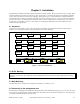
Chapter 3 - Understanding Your RAM-SAN 3.1 Interface Slot Numbering Each device in a RAM-SAN has a unique internal address based on the physical location of the device in the system. An interface’s port number can be determined by inspecting the back of the RAM-SAN (see Figure 1). 3.2 Inside the RAM-SAN You can open the top of the RAM-SAN by removing the screws on the lid of the system.
WARNING: Please exercise caution as you hot-swap power supplies for the RAM-SAN. Failure to follow these directions could result in injury or death. If you have any questions about this procedure, call Texas Memory Systems at 713-266-3200. 1. Turn off the power module that you plan to remove. Do not remove a hot swap power module from the chassis without turning the power module off. The master power switch can remain “ON” as can the other power modules. 2.
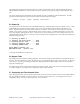
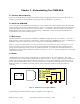
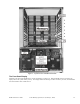
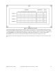
Figure 3 – Top-down View of RAM-SAN Internals The Front Panel Display Mounted on the front of the RAM-SAN is a front panel display (see Figure 4). When the RAM-SAN is in operation, the display reflects the system memory activity. The display monitors three things: location of memory accesses, bus bandwidth and which interface slots contain devices. RAM-SAN User’s Guide Texas Memory Systems, Inc.
Figure 4 – RAM-SAN Front Panel The RAM-SAN display consists of four rows of lights. Each row corresponds to one of the four RAM-SAN system busses. The top row corresponds to interface ports 0, 1, 2 and 3, the next row to ports 4, 5, 6 and 7, the next row to ports 8, 9, 10 and 11, and the bottom row corresponds to interface ports 12, 13, 14, and 15. When any device on a bus is active, a light turns on in the ADDRESSES section of the display corresponding to which gigabyte of memory it is accessing.
RAM-SAN User’s Guide Texas Memory Systems, Inc.
Chapter 4 – Configuring the RAM-SAN This chapter focuses on configuring the RAM-SAN. This includes configuring the Ethernet parameters, resizing LUNS, and performing LUN Masking. 4.1 The RAM-SAN Monitor The RAM-SAN is managed through an interactive command tool. The management software is accessed over Ethernet or the serial port on the RAM-SAN. See section 2.4 for more information on connecting the hardware. 4.
The amount of storage allocated to each Fibre Channel port may be changed using a simple configuration utility provided in the monitor. To enter this utility, type ‘partition’ on the monitor command line. You should see a message similar to this one: ram-san> ram-san> partition ** RAM-SAN partitioning utility ** Total memory size: 8192 Mb Command (h for help): To see a list of the available commands, type ‘h’ at the prompt.
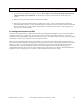
RAM-SAN 8 Gigabytes System Memory 3 Gigabyte drive 1 Fibre Channel ports HBA 1 3 Gigabyte drive 2 Gigabyte drive 2 FC21 HBA 2 3&4 FC21 HBA 3 HBA 4 4.3.2 Resizing LUNs The first step in changing the configuration is to resize the LUNs. Since our new configuration calls for three different LUNs, we need to use the ‘r’ command to resize LUNs. This command allows us to keep or delete the previous LUN mask and port assignments. This is useful if the only change is in the size of the LUNs.
Enter the LUN number: 1 Enter the Fibre Channel port: 5 Command (h for help): l Enter the LUN number: 2 Enter the Fibre Channel port: 5 Command (h for help): l Enter the LUN number: 3 Enter the Fibre Channel port: 9 Command (h for help): p Enter the LUN number (1-3, default is all): LUN 1 -- 3072 Mb ports: 5 access: Open access LUN 2 -- 3072 Mb ports: 5 access: Open access LUN 3 -- 2048 Mb ports: 9 access: Open access Command (h for help): From the last command, we can see that the port five has bee
4.3.5 Saving the Configuration to Flash RAM The RAM-SAN has now been configured to allow access from four different HBAs to 3 different LUNs within the memory system. To actually commit the change we have made, we can use the ‘w’ command to save the configuration into Flash RAM. You may also use the ‘q’ command to quit the partitioning utility without saving any changes. RAM-SAN User’s Guide Texas Memory Systems, Inc.
Chapter 5 – Using the Management Port The management port on the RAM-SAN allows an administrator to configure the system, monitor performance, and diagnose problems with the system. The ‘help’ command displays a list of commands available. The following sections provide a more detailed description of the commands available through the monitor. 5.1 testmem The ‘testmem’ command is used to verify the integrity of the system memory.
5.5 history The monitor maintains a volatile command history of the last 25 commands that have been entered. Using the ‘history’ command provides a listing of the history. Commands may be entered using the ‘<’ and ‘>’ keys to scroll through this history or the unix-like ‘!’ commands. The command history is volatile and will not be maintained between power cycles. 5.6 ipconfig The ‘ipconfig’ command allows for static IP configuration of the RAM-SAN.
5.13 status [port] The status command provides an overview of the RAM-SAN including Ethernet information, memory size, and the state of the Fibre Channel ports. The following output shows a sample status screen: ram-san> status Texas Memory Systems, Inc. RAM-SAN Monitor version 1.00 Ethernet address: 00:20:c2:00:07:f1 Ethernet IP: 192.94.231.
Chapter 6 - Troubleshooting This chapter is a quick troubleshooting guide for the most common RAM-SAN errors. To verify basic RAM-SAN operation, please consult Chapter 5 for instructions on running the system diagnostics. Below is a short list of RAM-SAN errors, symptoms and solutions. If this guide does not identify and correct your problem, please call Texas Memory Systems customer support at (713) 266-3200. 6.
6.2.1 MCP21 Does Not Display Characters If nothing is displayed on the dumb terminal connected to the RAM-SAN, try the following: • Check for solid serial cable connection at both the management and the debug monitor. • Be sure that the dumb terminal is set at 9600 baud, no parity, eight data bits, one stop bit, no flow control and US/CR terminator. • Try adding a null modem adapter to the serial connection. 6.2.
• the memory connector – the connector has a key to keep the memory board from going in backwards or awkwardly. Once in place, use the handles to evenly leverage the memory board into the slot. If none of the above hints helped, faulty hardware may exist. Follow the steps in section 6.4, Finding Bad Memory, and try to pinpoint which memory board has a problem. Then contact Texas Memory Systems customer support at (713)266-3200. 6.3.
Then repeat the steps above to confirm that the memory error followed the suspected board to the new board slot. Contact Texas Memory Systems with all the information you have found to begin actions to resolve the problem. 6.5 Confidence Diagnostic, DIAGMEM, Fails If the ‘testmem’ test produces error messages, use section 6.4 above to narrow down the problem to a specific memory board and, if possible, chip.
power glitches or a serious hardware failure. If a configuration LED stays lit after power-up, do the following: • • • • Verify that the oscillator is firmly inserted into its slot. The oscillator is located in the center of the system motherboard, between the connectors for memory slot 5. The writing on the oscillator should be oriented in the same direction as the text next to it on the motherboard that reads “50MHz” and “3.3V”.
Chapter 7 – Specifications This chapter contains system specifications for the RAM-SAN. 7.1 Physical Characteristics Rack Mount Size: Weight: Voltage: Ventilation: 7U (12.2”) x 25” deep 90 lbs. 110/220 VAC Side to side airflow 7.2 Operating Environment 32-85 °F (0-30 °C) 80% Temperature: Max relative humidity: (non-condensing) Max heat dissipation: Power consumption: 1700 Btu/hr (500 W) 100-550 W 7.
RAM-SAN User’s Guide Texas Memory Systems, Inc.