
Datasheet


Table Of Contents
- XTR108EVM-USB Evaluation Board and Software Tutorial
- 1 Overview
- 2 Hardware Overview
- 3 Hardware Setup
- 3.1 Electrostatic Discharge Warning
- 3.2 Connecting the Hardware
- 3.3 Connecting Power and USB to the USB DAQ Platform
- 3.4 Connecting Loop Power Supply to the XTR108EVM-USB Interface Board
- 3.5 Connecting Outputs to a Digital Multimeter (DMM)
- 3.6 USB DAQ Platform Default Jumper Settings
- 3.7 XTR108EVM-USB Interface Board Default Jumper Settings
- 3.8 XTR108EVM-USB Sensor Board Default Jumper Settings
- 4 Software Setup
- 5 Software Overview
- 6 General Operating Tips
- 7 Hardware Documentation
- 8 Appendix
- Important Notices
Windows PC
HP/Agilent 34401A DMM
+24V Power Supply
USB Cable
+6V Power Supply
(wall-wart)
XTR108EVM-USB
Interface Board
XTR108EVM-USB
Sensor Board
USB-DAQ
Platform
HI(F) LO(F) HI(S) LO(S) I(F)
Hardware Overview
www.ti.com
1.2 Related Documentation from Texas Instruments
The documents listed in Table 2 provide information regarding Texas Instruments' hardware used in
assembly of the XTR108EVM-USB. This user's guide is available from the TI web site under literature
number SBOU123. Any letter appended to the literature number corresponds to the document revision
that is current at the time of the writing of this document. Newer revisions may be available from the TI
web site at www.ti.com, or contact the Texas Instruments Product Information Center. Identify the
document by both title and literature number.
Table 2. Related Documentation
Document Literature Number
USB DAQ Platform user's guide SBOU056
XTR108 product data sheet SBOS187
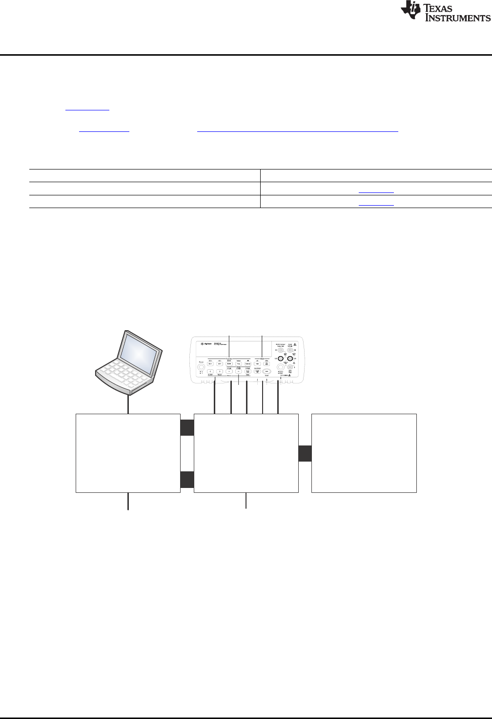
2 Hardware Overview
Figure 2 shows the XTR108EVM-USB system setup. The Windows™ PC runs software that
communicates with the USB DAQ Platform. The USB DAQ Platform generates the digital signals used to
communicate with the XTR108. The XTR108EVM-USB Interface Board routes digital communication and
analog input signals to the XTR108, provides a convenient interface to standard multimeters, and includes
an onboard RTD emulator circuit to facilitate calibration. The XTR108EVM-USB Sensor Board contains
the XTR108 device as well as support and configuration circuitry.
Figure 2. XTR108EVM-USB Hardware Setup
6
XTR108EVM-USB Evaluation Board and Software Tutorial SBOU123–March 2012
Submit Documentation Feedback
Copyright © 2012, Texas Instruments Incorporated