
Datasheet


Table Of Contents
- XTR108EVM-USB Evaluation Board and Software Tutorial
- 1 Overview
- 2 Hardware Overview
- 3 Hardware Setup
- 3.1 Electrostatic Discharge Warning
- 3.2 Connecting the Hardware
- 3.3 Connecting Power and USB to the USB DAQ Platform
- 3.4 Connecting Loop Power Supply to the XTR108EVM-USB Interface Board
- 3.5 Connecting Outputs to a Digital Multimeter (DMM)
- 3.6 USB DAQ Platform Default Jumper Settings
- 3.7 XTR108EVM-USB Interface Board Default Jumper Settings
- 3.8 XTR108EVM-USB Sensor Board Default Jumper Settings
- 4 Software Setup
- 5 Software Overview
- 6 General Operating Tips
- 7 Hardware Documentation
- 8 Appendix
- Important Notices
R
CM
R
Z2
R
Z3
R
Z4
R
Z5
R
Z1
+
PGA
XTR108
Multiplexer
V/I-5
V/I-4
V/I-3
V/I-2
V/I-1
V/I-0
I
1
I
2
Linearization
Circuit
Zero
DAC
I
LIN
DAC
I
REF
DAC
C
FILT
R
LIN
RTD
R
SET
0.01PF 34.0k:
12.1k:
R
CM
R
Z2
R
Z3
R
Z4
R
Z5
R
Z1
+
PGA
XTR108
Multiplexer
V/I-5
V/I-4
V/I-3
V/I-2
V/I-1
V/I-0
I
1
I
2
Linearization
Circuit
Zero
DAC
I
LIN
DAC
I
REF
DAC
C
FILT
R
LIN
RTD
R
SET
0.01PF 34.0k:
12.1k:
Appendix
www.ti.com
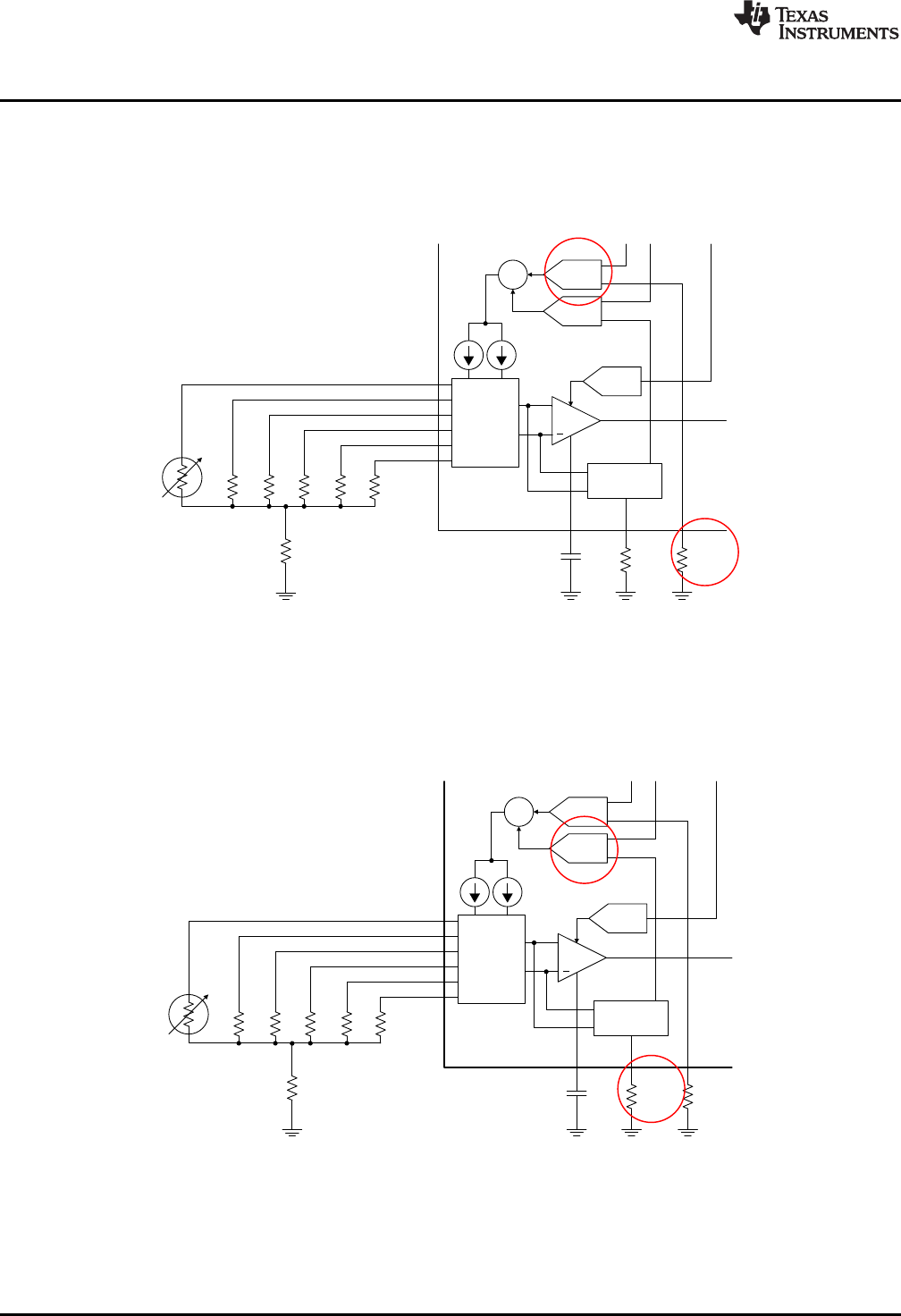
8.1.2 R
SET
The range of the I
REF
DAC that controls the current sources I
1
and I
2
is set by the external resistor R
SET
.
For example, with a value of R
SET
= 12.1 kΩ, the range of I
REF
is 480 µA to 510 µA. If R
SET
= 121 kΩ, the
range of I
REF
becomes 48 µA to 51 µA. The Find Resistors tab within the XTR108EVM-USB software
helps to determine the appropriate R
SET
value.
Figure 39. R
SET
Circuitry
8.1.3 R
LIN
All RTDs have a nonlinear response over temperature. Typically, this nonlinearity can be approximated as
a second-order function, and therefore can be calibrated out by modulating the excitation current with the
RTD input signal. The range of this linearity correction is set by external resistor, R
LIN
.
Figure 40. R
LIN
Circuitry
54
XTR108EVM-USB Evaluation Board and Software Tutorial SBOU123–March 2012
Submit Documentation Feedback
Copyright © 2012, Texas Instruments Incorporated