
Datasheet


Table Of Contents
- XTR108EVM-USB Evaluation Board and Software Tutorial
- 1 Overview
- 2 Hardware Overview
- 3 Hardware Setup
- 3.1 Electrostatic Discharge Warning
- 3.2 Connecting the Hardware
- 3.3 Connecting Power and USB to the USB DAQ Platform
- 3.4 Connecting Loop Power Supply to the XTR108EVM-USB Interface Board
- 3.5 Connecting Outputs to a Digital Multimeter (DMM)
- 3.6 USB DAQ Platform Default Jumper Settings
- 3.7 XTR108EVM-USB Interface Board Default Jumper Settings
- 3.8 XTR108EVM-USB Sensor Board Default Jumper Settings
- 4 Software Setup
- 5 Software Overview
- 6 General Operating Tips
- 7 Hardware Documentation
- 8 Appendix
- Important Notices
R
CM
523:
R
Z2
R
Z3
R
Z4
R
Z5
R
Z1
18.7:
RTD
PT100
+
PGA
XTR108
T=850°C
390.48:
500PA 500PA
I
1
I
2
V
CM =
0.52V
0.718V
0.532V
1000PA
500PA
500PA
Input differential voltage is
approximately 186mV at T
MAX
MUX
R
CM
5.23k:
R
Z2
R
Z3
R
Z4
R
Z5
R
Z1
187:
RTD
PT1000
+
PGA
XTR108
T=850°C
3.905k:
50PA 50PA
I
1
I
2
V
CM =
0.52V
0.718V
0.532V
100PA
50PA
50PA
Input differential voltage is
approximately 186mV at T
MAX
MUX
www.ti.com
Appendix
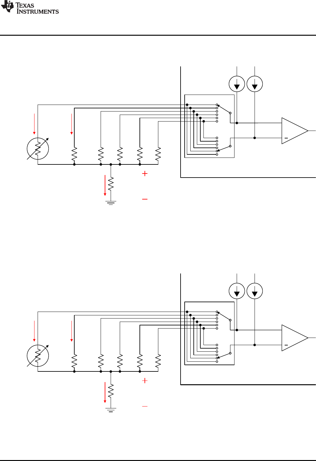
Figure 37 shows the same multiplexer configuration with the RTD at maximum temperature, where T
MAX
=
+850°C. At this point, the differential input voltage to the PGA is equal to 186 mV, the maximum value for
this configuration.
Figure 37. XTR108 Input MUX Example (T
MAX
= +850°C, PT100 RTD)
Figure 38 shows how the current sources can be programmed to accommodate different types of RTDs.
The previous example used a 100-Ω RTD, or PT100. In this example the RTD type has been changed to
1000 Ω, or PT1000. The current sources I
1
and I
2
are scaled from 500 µA to 50 µA to accommodate this
new resistance. R
Z1
and R
CM
are also scaled appropriately. Note that I
1
and I
2
are matched current sources
that are programmed by one set of DACs (an 8-bit coarse DAC and 8-bit fine DAC). These current
sources are programmed during the calibration procedure.
Figure 38. XTR108 Input MUX Example (T
MAX
= +850°C, PT1000 RTD)
53
SBOU123–March 2012 XTR108EVM-USB Evaluation Board and Software Tutorial
Submit Documentation Feedback
Copyright © 2012, Texas Instruments Incorporated