
Datasheet


Table Of Contents
- XTR108EVM-USB Evaluation Board and Software Tutorial
- 1 Overview
- 2 Hardware Overview
- 3 Hardware Setup
- 3.1 Electrostatic Discharge Warning
- 3.2 Connecting the Hardware
- 3.3 Connecting Power and USB to the USB DAQ Platform
- 3.4 Connecting Loop Power Supply to the XTR108EVM-USB Interface Board
- 3.5 Connecting Outputs to a Digital Multimeter (DMM)
- 3.6 USB DAQ Platform Default Jumper Settings
- 3.7 XTR108EVM-USB Interface Board Default Jumper Settings
- 3.8 XTR108EVM-USB Sensor Board Default Jumper Settings
- 4 Software Setup
- 5 Software Overview
- 6 General Operating Tips
- 7 Hardware Documentation
- 8 Appendix
- Important Notices
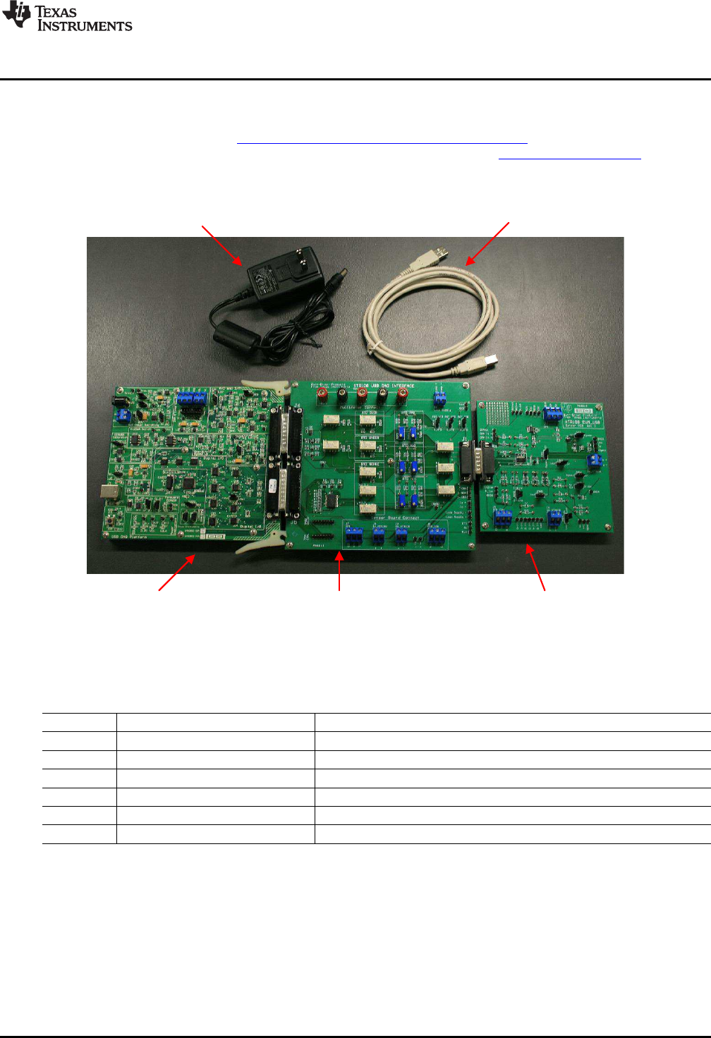
+6V Power Supply
(wall-wart)
USB Cable
USB DAQ
Platform
XTR108EVM-USB
Interface Board
XTR108EVM-USB
Sensor Board
www.ti.com
Overview
1.1 XTR108EVM-USB Kit Contents
Figure 1 shows the hardware included with the XTR108EVM-USB kit. Table 1 describes each item
included in the kit. Contact the Texas Instruments Product Information Center nearest you if any
component is missing. It is highly recommended that you also check the XTR108 product folder to verify
that you have the latest version of the related software.
Figure 1. Hardware Included with the XTR108EVM-USB
Table 1. XTR108EVM-USB Kit Contents
Quantity Item Description
1 USB DAQ Platform Digital communications board
1 XTR108EVM-USB Interface Board XTR108EVM-USB Interface Board with required populated components
1 XTR108EVM-USB Sensor Board XTR108EVM-USB Sensor Board with required populated components
1 USB cable Connects PC to USB DAQ Platform
1 +6-V power supply (wall-wart) Provides power to USB DAQ Platform
1 Software installation disk Contains required software and documentation
5
SBOU123–March 2012 XTR108EVM-USB Evaluation Board and Software Tutorial
Submit Documentation Feedback
Copyright © 2012, Texas Instruments Incorporated