
Datasheet


Table Of Contents
- XTR108EVM-USB Evaluation Board and Software Tutorial
- 1 Overview
- 2 Hardware Overview
- 3 Hardware Setup
- 3.1 Electrostatic Discharge Warning
- 3.2 Connecting the Hardware
- 3.3 Connecting Power and USB to the USB DAQ Platform
- 3.4 Connecting Loop Power Supply to the XTR108EVM-USB Interface Board
- 3.5 Connecting Outputs to a Digital Multimeter (DMM)
- 3.6 USB DAQ Platform Default Jumper Settings
- 3.7 XTR108EVM-USB Interface Board Default Jumper Settings
- 3.8 XTR108EVM-USB Sensor Board Default Jumper Settings
- 4 Software Setup
- 5 Software Overview
- 6 General Operating Tips
- 7 Hardware Documentation
- 8 Appendix
- Important Notices
V
CC
JMP7
CP SCK
NO CLK
SPI_SCK
C11
R11
C13
U3
D2
C12
R10
XTR108 I
IN
330pF 30.1k
36.5k
1nF
0.01PF
JMP6
BYPASS
BUF
www.ti.com
General Operating Tips
6 General Operating Tips
6.1 Voltage Output Mode
In many applications, it is desirable to bypass the FET and connect the XTR108 directly to the power
supply. This configuration can be completed by positioning jumpers JMP2 and JMP3 in the Bypass
position.
NOTE: You must be careful in this mode to not apply an overvoltage to the XTR108. The XTR108
maximum supply voltage is 5.5 V. The voltage drop across D1 reduces the XTR108 supply
voltage by approximately 0.7 V. To get an accurate idea of the XTR108 supply voltage while
in this mode, you should measure at the XTR108 V
S
pin.
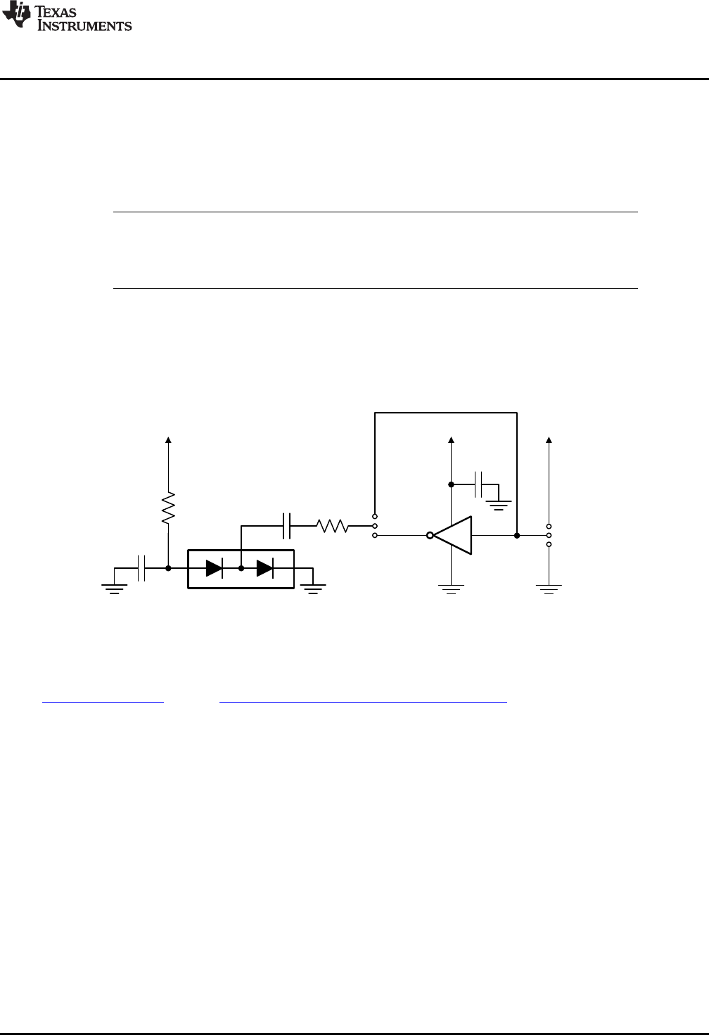
6.2 Charge Pump
When the XTR108 is in voltage-output mode, a small negative voltage must be applied to the XTR108 I
IN
pin to prevent the input offset voltage of the XTR108 current output stage from turning on the output
stage. A simple discrete charge pump circuit, shown in Figure 33, can be used to generate this small
negative voltage. The charge pump input is the SPI clock to the XTR108.
Figure 33. Discrete Charge Pump on Sensor Interface Board
For this circuit to work, the XTR108 clock must toggle continuously. This toggling can be accomplished by
keeping the XTR108 in continuous EEPROM read mode. JMP6 can be used to connect or disconnect an
external buffer to the XTR108 clock signal. More information regarding this charge pump is located in the
XTR108 data sheet and the XTR108 Quick Start System Reference Guide.
47
SBOU123–March 2012 XTR108EVM-USB Evaluation Board and Software Tutorial
Submit Documentation Feedback
Copyright © 2012, Texas Instruments Incorporated