
Datasheet


Table Of Contents
- XTR108EVM-USB Evaluation Board and Software Tutorial
- 1 Overview
- 2 Hardware Overview
- 3 Hardware Setup
- 3.1 Electrostatic Discharge Warning
- 3.2 Connecting the Hardware
- 3.3 Connecting Power and USB to the USB DAQ Platform
- 3.4 Connecting Loop Power Supply to the XTR108EVM-USB Interface Board
- 3.5 Connecting Outputs to a Digital Multimeter (DMM)
- 3.6 USB DAQ Platform Default Jumper Settings
- 3.7 XTR108EVM-USB Interface Board Default Jumper Settings
- 3.8 XTR108EVM-USB Sensor Board Default Jumper Settings
- 4 Software Setup
- 5 Software Overview
- 6 General Operating Tips
- 7 Hardware Documentation
- 8 Appendix
- Important Notices
www.ti.com
Software Overview
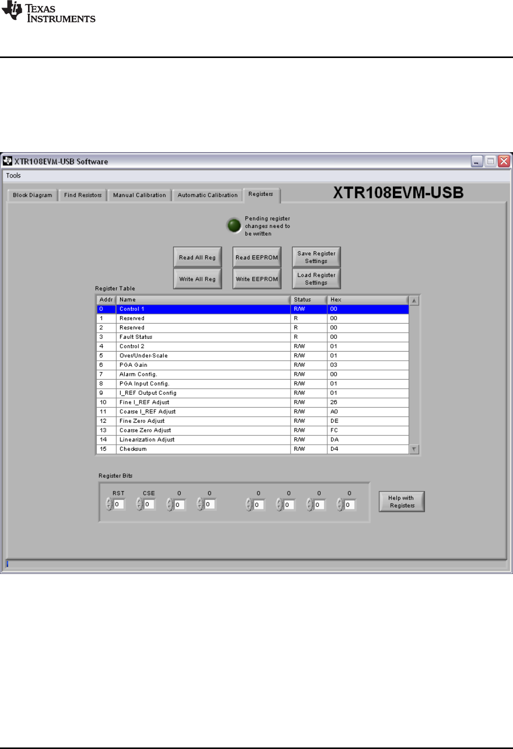
5.5 Registers Tab
The Registers tab in the XTR108EVM-USB software enables the user to view and edit the contents of
each register internal to the XTR108. Similar to the Block Diagram tab, it is recommended that only
advanced users make bit-level changes using this tab. However, for debugging purposes this capability
can be extremely useful.
Figure 29 shows the Registers tab. The actual values of each register may vary.
Figure 29. XTR108EVM-USB Software, Registers Tab
43
SBOU123–March 2012 XTR108EVM-USB Evaluation Board and Software Tutorial
Submit Documentation Feedback
Copyright © 2012, Texas Instruments Incorporated