
Datasheet


Table Of Contents
- XTR108EVM-USB Evaluation Board and Software Tutorial
- 1 Overview
- 2 Hardware Overview
- 3 Hardware Setup
- 3.1 Electrostatic Discharge Warning
- 3.2 Connecting the Hardware
- 3.3 Connecting Power and USB to the USB DAQ Platform
- 3.4 Connecting Loop Power Supply to the XTR108EVM-USB Interface Board
- 3.5 Connecting Outputs to a Digital Multimeter (DMM)
- 3.6 USB DAQ Platform Default Jumper Settings
- 3.7 XTR108EVM-USB Interface Board Default Jumper Settings
- 3.8 XTR108EVM-USB Sensor Board Default Jumper Settings
- 4 Software Setup
- 5 Software Overview
- 6 General Operating Tips
- 7 Hardware Documentation
- 8 Appendix
- Important Notices
Software Overview
www.ti.com
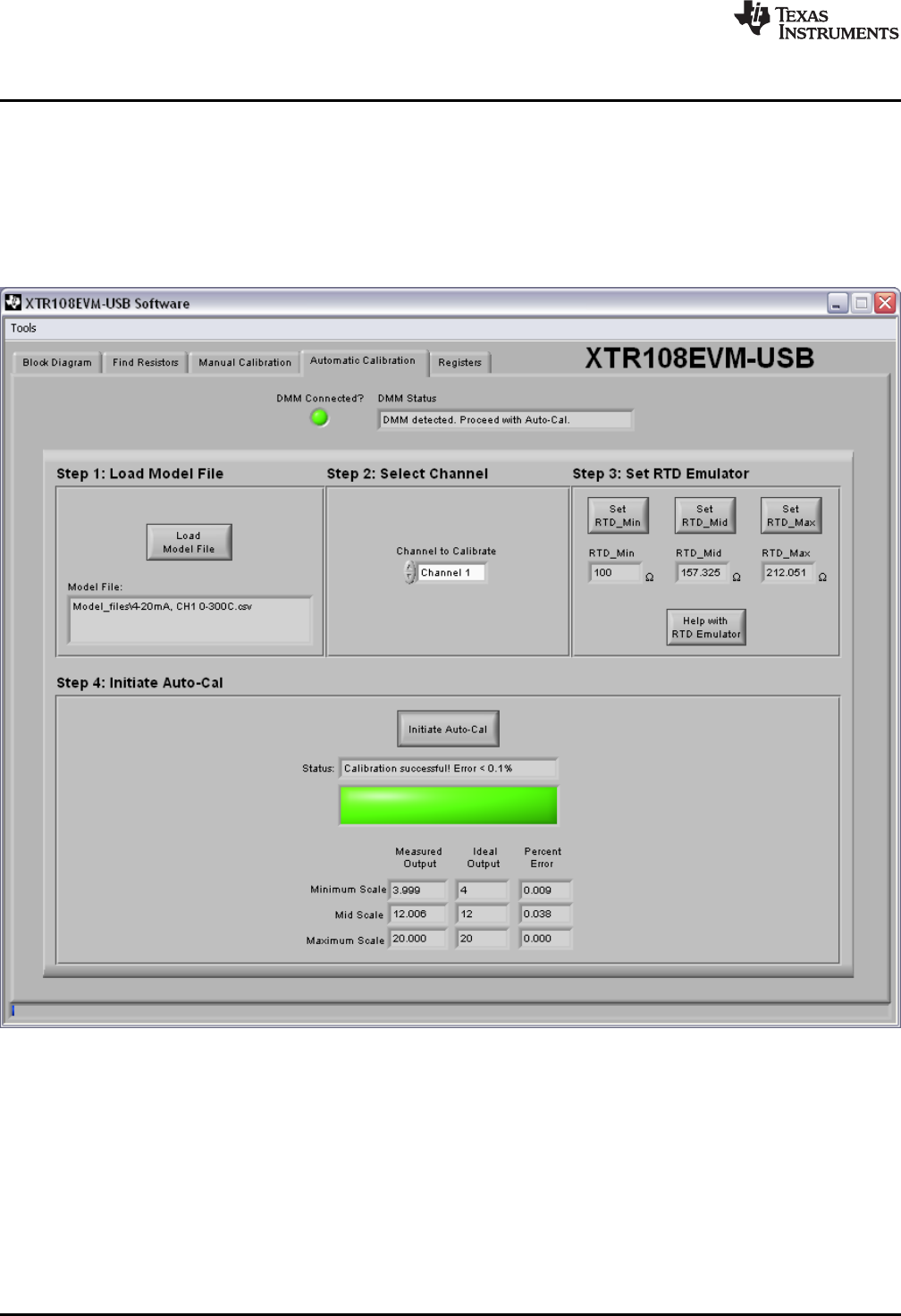
5.4.6 Verify Calibration
If the percentage of minimum-scale, mid-scale, and maximum-scale error after calibration is less than or
equal to 0.1%, the Status indicator displays the message Calibration successful! Error < 0.1% and the
square status LED turns on (bright green). Figure 28 shows an example of a successful post-calibration
screen.
If the percentage of error after calibration is greater than 0.1%, the Status indicator displays the message
Calibration unsuccessful. Error > 0.1% and the square status LED turns on (red).
Figure 28. Automatic Calibration Tab, Post-Calibration
42
XTR108EVM-USB Evaluation Board and Software Tutorial SBOU123–March 2012
Submit Documentation Feedback
Copyright © 2012, Texas Instruments Incorporated