
Datasheet


Table Of Contents
- XTR108EVM-USB Evaluation Board and Software Tutorial
- 1 Overview
- 2 Hardware Overview
- 3 Hardware Setup
- 3.1 Electrostatic Discharge Warning
- 3.2 Connecting the Hardware
- 3.3 Connecting Power and USB to the USB DAQ Platform
- 3.4 Connecting Loop Power Supply to the XTR108EVM-USB Interface Board
- 3.5 Connecting Outputs to a Digital Multimeter (DMM)
- 3.6 USB DAQ Platform Default Jumper Settings
- 3.7 XTR108EVM-USB Interface Board Default Jumper Settings
- 3.8 XTR108EVM-USB Sensor Board Default Jumper Settings
- 4 Software Setup
- 5 Software Overview
- 6 General Operating Tips
- 7 Hardware Documentation
- 8 Appendix
- Important Notices
Software Overview
www.ti.com
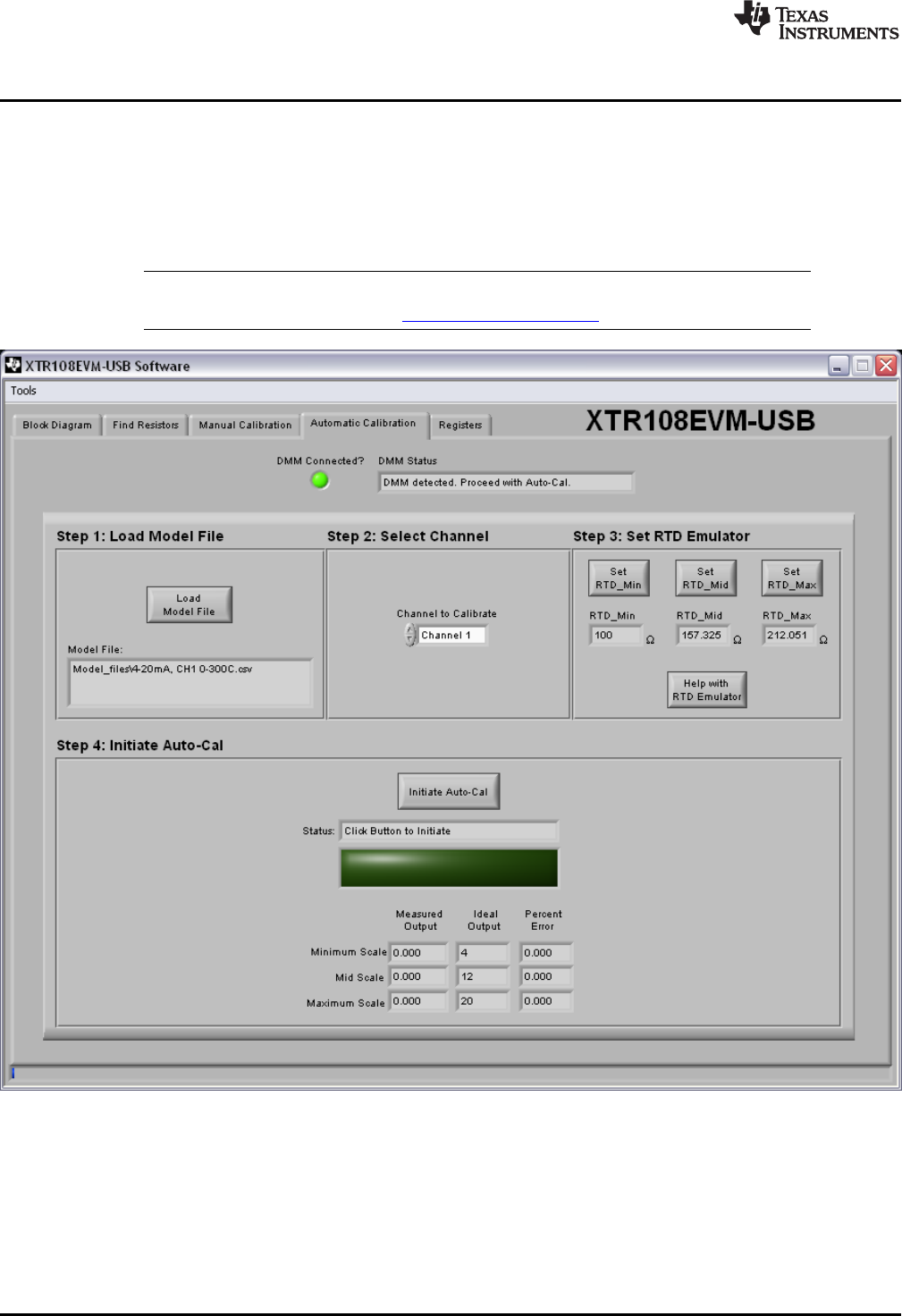
5.4 Automatic Calibration Tab
The Automatic Calibration tab in the XTR108EVM-USB software allows the user to perform a completely
automated calibration of the XTR108 using a previously-saved model file. The entire procedure takes less
than a minute to complete and only requires the user to click one button.
Figure 27 shows the Automatic Calibration tab. The following sections explain the use of each section of
the tab.
NOTE: Use of the Automatic Calibration tab requires that an Agilent 34401A multimeter be
connected to the user PC using the NI GPIB-USB-HS controller, available separately.
Figure 27. XTR108EVM-USB Software, Automatic Calibration Tab
40
XTR108EVM-USB Evaluation Board and Software Tutorial SBOU123–March 2012
Submit Documentation Feedback
Copyright © 2012, Texas Instruments Incorporated