
Datasheet


Table Of Contents
- XTR108EVM-USB Evaluation Board and Software Tutorial
- 1 Overview
- 2 Hardware Overview
- 3 Hardware Setup
- 3.1 Electrostatic Discharge Warning
- 3.2 Connecting the Hardware
- 3.3 Connecting Power and USB to the USB DAQ Platform
- 3.4 Connecting Loop Power Supply to the XTR108EVM-USB Interface Board
- 3.5 Connecting Outputs to a Digital Multimeter (DMM)
- 3.6 USB DAQ Platform Default Jumper Settings
- 3.7 XTR108EVM-USB Interface Board Default Jumper Settings
- 3.8 XTR108EVM-USB Sensor Board Default Jumper Settings
- 4 Software Setup
- 5 Software Overview
- 6 General Operating Tips
- 7 Hardware Documentation
- 8 Appendix
- Important Notices
Software Overview
www.ti.com
5.2.2 Step 2: Calculate Resistor Values
When the Calculate Resistors button is clicked, the XTR108EVM-USB software uses the operating
conditions entered in Step 1: Enter Operating Commands to calculate the best values for R
SET
, R
LIN
, R
CM
,
and R
Z
(for each enabled channel).
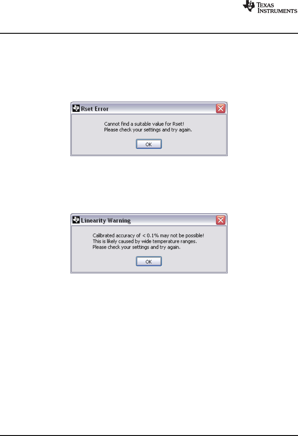
The R
SET
value is critical to proper XTR108 operation (see the I_REF DAC section). If the software cannot
find a suitable R
SET
value, an error message is displayed as shown in Figure 21. This error is typically
caused by narrow or conflicting temperature ranges on multiple channels. If you encounter this error,
widen your temperature ranges slightly and click the Calculate Resistors button again.
Figure 21. R
SET
Error
The XTR108EVM-USB software also performs a linearity check as part of the Calculate Resistors
functionality. If the software predicts that a post-calibrated error less than 0.1% of full-scale is not possible,
a warning message is displayed as shown in Figure 22. This error is typically caused by very wide
temperature ranges on multiple channels. If you encounter this warning, narrow your temperature ranges
slightly and click the Calculate Resistors button again.
Figure 22. Linearity Warning
5.2.3 Step 3: Install These Resistors
This area of the Find Resistors tab displays the calculated resistor values for R
SET
, R
LIN
, R
CM
, and R
Z
(for
each enabled channel). Install these resistors on the XTR108EVM-USB Sensor Board, either by soldering
surface-mount resistors or installing through-hole resistors in the pin sockets. The R
Z
indicator for disabled
channels is grayed out.
34
XTR108EVM-USB Evaluation Board and Software Tutorial SBOU123–March 2012
Submit Documentation Feedback
Copyright © 2012, Texas Instruments Incorporated