
Datasheet


Table Of Contents
- XTR108EVM-USB Evaluation Board and Software Tutorial
- 1 Overview
- 2 Hardware Overview
- 3 Hardware Setup
- 3.1 Electrostatic Discharge Warning
- 3.2 Connecting the Hardware
- 3.3 Connecting Power and USB to the USB DAQ Platform
- 3.4 Connecting Loop Power Supply to the XTR108EVM-USB Interface Board
- 3.5 Connecting Outputs to a Digital Multimeter (DMM)
- 3.6 USB DAQ Platform Default Jumper Settings
- 3.7 XTR108EVM-USB Interface Board Default Jumper Settings
- 3.8 XTR108EVM-USB Sensor Board Default Jumper Settings
- 4 Software Setup
- 5 Software Overview
- 6 General Operating Tips
- 7 Hardware Documentation
- 8 Appendix
- Important Notices
Hardware Setup
www.ti.com
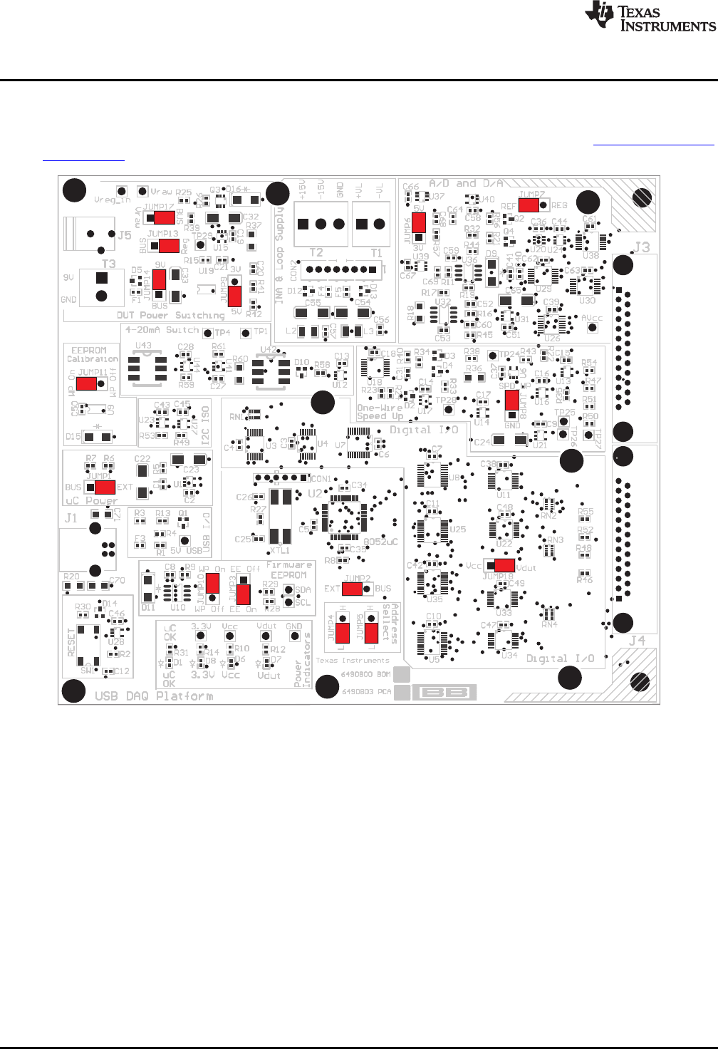
3.6 USB DAQ Platform Default Jumper Settings
Figure 14 shows the default USB DAQ Platform jumper configuration. In general, these jumpers should
not be changed. For more information about the function of these jumpers, refer to the USB DAQ Platform
User's Guide.
Figure 14. USB DAQ Platform Default Jumper Settings
22
XTR108EVM-USB Evaluation Board and Software Tutorial SBOU123–March 2012
Submit Documentation Feedback
Copyright © 2012, Texas Instruments Incorporated