
Datasheet


Table Of Contents
- XTR108EVM-USB Evaluation Board and Software Tutorial
- 1 Overview
- 2 Hardware Overview
- 3 Hardware Setup
- 3.1 Electrostatic Discharge Warning
- 3.2 Connecting the Hardware
- 3.3 Connecting Power and USB to the USB DAQ Platform
- 3.4 Connecting Loop Power Supply to the XTR108EVM-USB Interface Board
- 3.5 Connecting Outputs to a Digital Multimeter (DMM)
- 3.6 USB DAQ Platform Default Jumper Settings
- 3.7 XTR108EVM-USB Interface Board Default Jumper Settings
- 3.8 XTR108EVM-USB Sensor Board Default Jumper Settings
- 4 Software Setup
- 5 Software Overview
- 6 General Operating Tips
- 7 Hardware Documentation
- 8 Appendix
- Important Notices
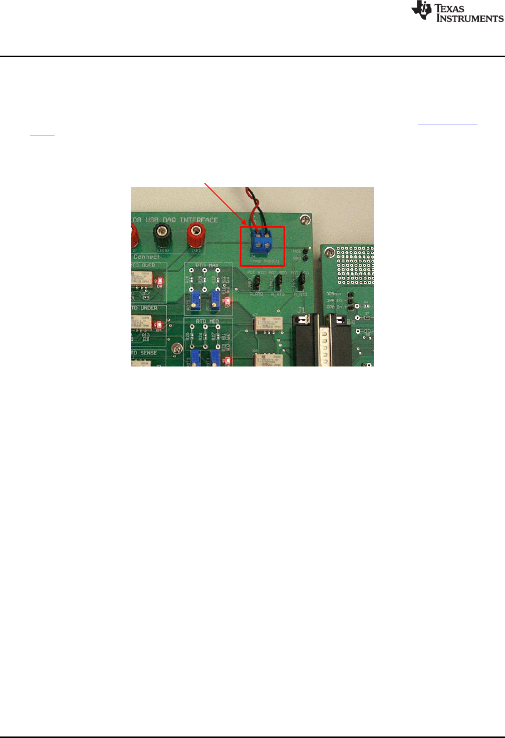
Connect DC Lab
Power Supply to J4
I
OUT
Mode: 12V to 24V
V
OUT
Mode: 3V to 5.5V
Hardware Setup
www.ti.com
3.4 Connecting Loop Power Supply to the XTR108EVM-USB Interface Board
Connect a dc lab power supply to J4 on the Interface Board as shown in Figure 12. When operating in
current-output mode, the loop-supply input voltage range is 12 V to 24 V. In general, you must consider
the power dissipated in the external transistor and the operating temperature of the transistor in order to
determine the maximum loop voltage and current. This calculation is determined in the XTR108 data
sheet. When operating in voltage-output mode, the loop-supply input voltage range is (3.0 V to 5.5 V) +
V
D1
.
Figure 12. Connecting a Loop Power Supply to the XTR108EVM-USB Interface Board
20
XTR108EVM-USB Evaluation Board and Software Tutorial SBOU123–March 2012
Submit Documentation Feedback
Copyright © 2012, Texas Instruments Incorporated