
Datasheet


Table Of Contents
- XTR108EVM-USB Evaluation Board and Software Tutorial
- 1 Overview
- 2 Hardware Overview
- 3 Hardware Setup
- 3.1 Electrostatic Discharge Warning
- 3.2 Connecting the Hardware
- 3.3 Connecting Power and USB to the USB DAQ Platform
- 3.4 Connecting Loop Power Supply to the XTR108EVM-USB Interface Board
- 3.5 Connecting Outputs to a Digital Multimeter (DMM)
- 3.6 USB DAQ Platform Default Jumper Settings
- 3.7 XTR108EVM-USB Interface Board Default Jumper Settings
- 3.8 XTR108EVM-USB Sensor Board Default Jumper Settings
- 4 Software Setup
- 5 Software Overview
- 6 General Operating Tips
- 7 Hardware Documentation
- 8 Appendix
- Important Notices
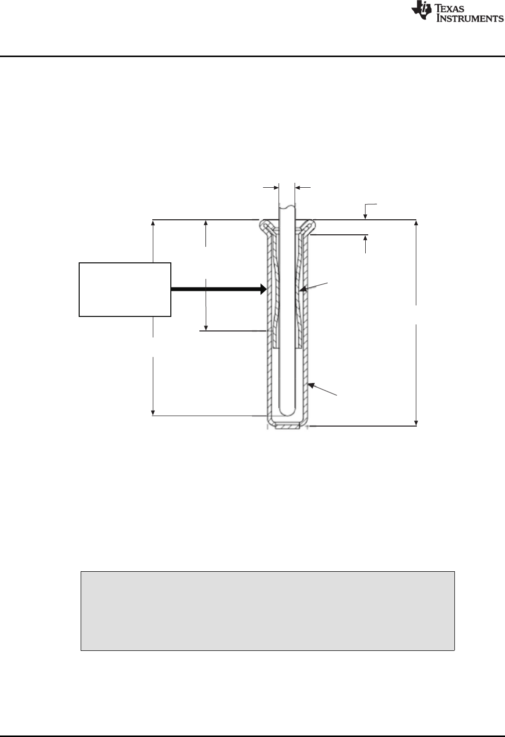
Through-holelead
makescontactto
pinsocketwith
springaction.
PINDIA
0.36-0.56
[.014-.022]
SPRING
EYELET
6.60
[.260]
2.54
[.100]
CONTACTPT
MIN
6.27
[.247]MAXPINLENGTH
Hardware Setup
www.ti.com
2.3.3 Test Points and Miscellaneous Breadboard Area
There are multiple points available on the Sensor Board, including several connections to I
RET
. I
RET
is
common (labeled as GND on the board) for most XTR108 applications, and is provided for ease of
measuring analog signals. Reserved areas with plated-through, standard-spacing, 0.1-inch holes for
miscellaneous proof-of-concept breadboarding are also provided on the board. Most of the surface-mount
components have pin sockets associated with them. These pin sockets allow the replacement of a
surface-mount component with a through-hole component.
The pin sockets provide good contact with the leads of a component without solder, thus enabling quick
reconfiguration of the board for many different XTR108 designs, as shown in Figure 6.
Figure 6. Pin Socket Mechanical Description
3 Hardware Setup
The XTR108EVM-USB hardware setup involves connecting the three EVM boards together, applying
power to the USB DAQ platform, connecting the USB cable, applying power to the Interface Board, and
setting the jumpers. This section covers the details of this procedure.
3.1 Electrostatic Discharge Warning
CAUTION
Many of the components on the XTR108EVM-USB are susceptible to damage
by electrostatic discharge (ESD). Customers are advised to observe proper
ESD handling precautions when unpacking and handling the EVM, including
the use of a grounded wrist strap at an approved ESD workstation.
16
XTR108EVM-USB Evaluation Board and Software Tutorial SBOU123–March 2012
Submit Documentation Feedback
Copyright © 2012, Texas Instruments Incorporated