
Datasheet


Table Of Contents
- XTR108EVM-USB Evaluation Board and Software Tutorial
- 1 Overview
- 2 Hardware Overview
- 3 Hardware Setup
- 3.1 Electrostatic Discharge Warning
- 3.2 Connecting the Hardware
- 3.3 Connecting Power and USB to the USB DAQ Platform
- 3.4 Connecting Loop Power Supply to the XTR108EVM-USB Interface Board
- 3.5 Connecting Outputs to a Digital Multimeter (DMM)
- 3.6 USB DAQ Platform Default Jumper Settings
- 3.7 XTR108EVM-USB Interface Board Default Jumper Settings
- 3.8 XTR108EVM-USB Sensor Board Default Jumper Settings
- 4 Software Setup
- 5 Software Overview
- 6 General Operating Tips
- 7 Hardware Documentation
- 8 Appendix
- Important Notices
Hardware Overview
www.ti.com
2.3.1 Sensor Board Connections
This section provides signal definitions for all XTR108EVM-USB Interface Board connectors.
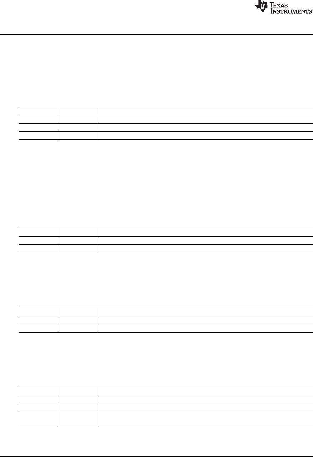
2.3.1.1 J1 (SPI)
Table 13 shows the signals connected to J1 on the Sensor Board. J1 is used to connect an external SPI
interface to the Sensor Board.
Table 13. J1 Pinout (SPI)
Pin Name Description
1 CS1 SPI chip select
2 SCK SPI clock
3 SDIO SPI data input/output
2.3.1.2 J2 (15-pin Male DSUB)
J2 is the connection for all input and output signals between the Interface Board and Sensor Board. See
Table 4 for pinout information.
2.3.1.3 J3 (Io_XTR108)
Table 14 shows the signals connected to J3 on the Sensor Board. J3 is used to connect an external loop
power supply to the Sensor Board and to connect the XTR108 current output to an external ammeter.
Table 14. J3 Pinout (Io_XTR108)
Pin Name Description
1 IO– Low-side loop power-supply and current output from the XTR108
2 IO+ High-side loop power-supply and current output from the XTR108
2.3.1.4 J4 (Vo_XTR108)
Table 15 shows the signals connected to J4 on the Sensor Board. J4 is used to connect the XTR108
voltage output to an external voltmeter.
Table 15. J4 Pinout (Vo_XTR108)
Pin Name Description
1 VO+ High-side voltage output from the XTR108
2 VO– Low-side voltage output from the XTR108
2.3.1.5 J5 (RTD_CON)
Table 16 shows the signals connected to J5 on the Sensor Board. J5 is used to connect an external RTD
to the Sensor Board.
Table 16. J5 Pinout (RTD_CON)
Pin Name Description
1 RTD RTD resistance. Connect the red wire of a two- or three-wire RTD here.
2 RZ R
Z
(zero-scale resistor). Connect the black wire of a two- or three-wire RTD here.
R
CM
(common-mode resistor). Short to pin 2 (RZ) if using a two-wire RTD. Connect the second
3 RCM
black wire here if using a three-wire RTD.
14
XTR108EVM-USB Evaluation Board and Software Tutorial SBOU123–March 2012
Submit Documentation Feedback
Copyright © 2012, Texas Instruments Incorporated