
Datasheet


Table Of Contents
- XTR108EVM-USB Evaluation Board and Software Tutorial
- 1 Overview
- 2 Hardware Overview
- 3 Hardware Setup
- 3.1 Electrostatic Discharge Warning
- 3.2 Connecting the Hardware
- 3.3 Connecting Power and USB to the USB DAQ Platform
- 3.4 Connecting Loop Power Supply to the XTR108EVM-USB Interface Board
- 3.5 Connecting Outputs to a Digital Multimeter (DMM)
- 3.6 USB DAQ Platform Default Jumper Settings
- 3.7 XTR108EVM-USB Interface Board Default Jumper Settings
- 3.8 XTR108EVM-USB Sensor Board Default Jumper Settings
- 4 Software Setup
- 5 Software Overview
- 6 General Operating Tips
- 7 Hardware Documentation
- 8 Appendix
- Important Notices
www.ti.com
Hardware Overview
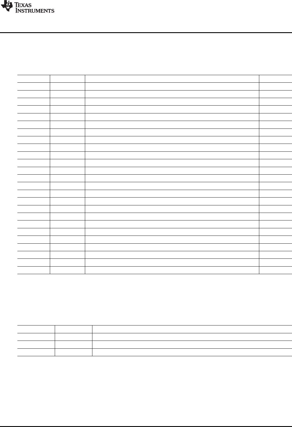
2.2.1.7 J6 (25-Pin Male DSUB)
Table 9 shows the signals connected to J6 on the Interface Board. J6 is used to connect the SPI interface
and 5.0-V power supply from the USB DAQ to the Interface Board.
Table 9. J6 Pinout (25-Pin Male DSUB)
Pin Name Description Used
1 DAC_A DAC_A output No
2 DAC_B DAC_B output No
3 DAC_C DAC_C output No
4 DAC_D DAC_D output No
5 ADS1_VIN+ ADS1 positive input No
6 ADS1_VIN– ADS1 negative input No
7 ADS2_VIN+ ADS2 positive input No
8 ADS2_VIN– ADS2 negative input No
9 I2C_SCK I
2
C clock No
10 I2C_SDA I
2
C data No
11 ONE_WIRE One-wire communication line No
12 I2C_SDA_ISO I
2
C data (isolated) No
13 I2C_SCK_ISO I
2
C clock (isolated) No
14 XTR +LOOP Current-loop high-side input No
15 XTR –LOOP Current-loop low-side input No
16 INA– INA negative input No
17 VDUT Selectable 3.3-V or 5.0-V power supply No
18 VCC 5.0-V power supply Yes
19 +15V +15-V power supply No
20 –15V –15-V power supply No
21 GND Ground Yes
22 SPI_SCK SPI clock, channel 1 Yes
23 SPI_CS1 SPI chip select, channel 1 Yes
24 SPI_DOUT SPI data output, channel 1 Yes
25 SPI_DIN1 SPI data input, channel 1 Yes
2.2.1.8 J7 (SPI)
Table 10 shows the signals connected to J7 on the Interface Board. J7 is used to connect the SPI
interface to an external XTR108 system.
Table 10. J7 Pinout (SPI)
Pin Name Description
1 DIO SPI data input/output
2 SCK SPI clock
3 CS1 SPI chip select
11
SBOU123–March 2012 XTR108EVM-USB Evaluation Board and Software Tutorial
Submit Documentation Feedback
Copyright © 2012, Texas Instruments Incorporated