
Datasheet


Table Of Contents
- XTR108EVM-USB Evaluation Board and Software Tutorial
- 1 Overview
- 2 Hardware Overview
- 3 Hardware Setup
- 3.1 Electrostatic Discharge Warning
- 3.2 Connecting the Hardware
- 3.3 Connecting Power and USB to the USB DAQ Platform
- 3.4 Connecting Loop Power Supply to the XTR108EVM-USB Interface Board
- 3.5 Connecting Outputs to a Digital Multimeter (DMM)
- 3.6 USB DAQ Platform Default Jumper Settings
- 3.7 XTR108EVM-USB Interface Board Default Jumper Settings
- 3.8 XTR108EVM-USB Sensor Board Default Jumper Settings
- 4 Software Setup
- 5 Software Overview
- 6 General Operating Tips
- 7 Hardware Documentation
- 8 Appendix
- Important Notices
Hardware Overview
www.ti.com
2.2.1.4 J3 (Io_XTR108)
Table 6 shows the signals connected to J3 on the Interface Board. J3 is used to connect the current
output of an external XTR108 system to the Interface Board.
Table 6. J3 Pinout (Io_XTR108)
Pin Name Description
1 IO+ High-side current output from the XTR108
2 IO– Low-side current output from the XTR108
2.2.1.5 J4 (Loop Supply)
Table 7 shows the signals connected to J4 on the Interface Board. J4 provides the loop power supply to
the XTR108.
Table 7. J4 Pinout (Loop Supply)
Pin Name Description
1 LOOP– Low-side loop power supply
2 LOOP+ High-side loop power supply
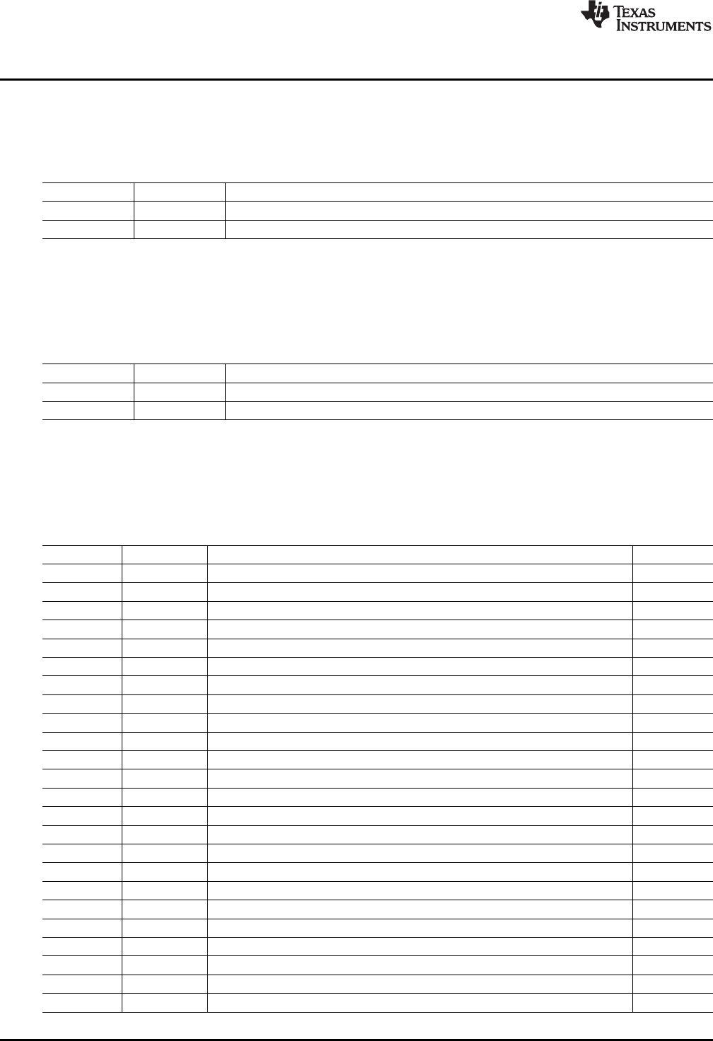
2.2.1.6 J5 (25-Pin Female DSUB)
Table 8 shows the signals connected to J5 on the Interface Board. J5 is used to connect the USB DAQ
control signals to the Interface Board.
Table 8. J5 Pinout (25-Pin Female DSUB)
Pin Name Description Used
1 NC No connection No
2 CTRL1 Control signal 1 Yes
3 CTRL2 Control signal 1 Yes
4 CTRL3 Control signal 1 Yes
5 CTRL4 Control signal 1 Yes
6 CTRL5 Control signal 1 Yes
7 CTRL6 Control signal 1 Yes
8 CTRL7 Control signal 1 Yes
9 CTRL8 Control signal 1 Yes
10 MEAS1 Measure input 1 No
11 MEAS2 Measure input 1 No
12 MEAS3 Measure input 1 No
13 MEAS4 Measure input 1 No
14 MEAS5 Measure input 1 No
15 MEAS6 Measure input 1 No
16 MEAS7 Measure input 1 No
17 MEAS8 Measure input 1 No
18 SPI_SCK SPI clock, channel 2 No
19 SPI_CS2 SPI chip select, channel 2 No
20 SPI_DOUT2 SPI data output, channel 2 No
21 SPI_DIN2 SPI data input, channel 2 No
22 VDUT Switched power supply No
23 VCC USB DAQ power supply No
24, 25 GND Ground No
10
XTR108EVM-USB Evaluation Board and Software Tutorial SBOU123–March 2012
Submit Documentation Feedback
Copyright © 2012, Texas Instruments Incorporated