
PCI Express Switch User's Guide

1.4 ExpressCard-Mode operation
www.ti.com
ExpressCard-Mode operation
• General control register (PCI register offset: D4h in port 1 and port 2 downstream bridges)
– RCVR_PRSNT_EN = 0b – PRSNT pin is used to determine whether slot is present
– REFCK_DIS = 0b – REFCK enabled
– LINK_ACT_RPT_CAP = 1b – Slot is link active reporting capable
– SLOT_PFIP = 1b – Power fault input implemented
– SLOT_PRSNT = 1b – Port connected to slot
– SLOT_ABP = 1b – Attention button implemented
– SLOT_PCP = 1b – Power controller implemented
– SLOT_AIP = 1b – Attention indicator implemented
– SLOT_PIP = 1b – Power indicator implemented
– SLOT_HPS = 1b – Device present that can be removed without prior notification.
– SLOT_HPC = 1b – Slot is hot-plug capable
– RC_PF_CTL = 1b – REFCK output enable is a function of PWR_FAULT
• General control register (PCI register offset: D4h in port 3 downstream bridge)
– RCVR_PRSNT_EN = 0b – PRSNT pin is used to determine whether slot is present
– REFCK_DIS = 0b – REFCK enabled
– LINK_ACT_RPT_CAP = 1b – Slot is link active reporting capable
– SLOT_PRSNT = 1b – Port connected to slot
• General slot info register (PCI register offset EEh in each downstream bridge)
– SLOT_NUM = 1b for slot 1, 2b for slot 2, and 3b for slot 3
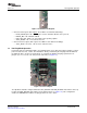
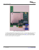
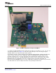
For this mode of operation, the ExpressCard adapter board is used in conjunction with the XIO3130 EVM
board. This adapter board utilizes the TI TPS2231 power interface switch to switch power on and off to the
ExpressCard slot. TI also offers a dual-power interface switch called the TPS2236. Figure 1-8 shows the
adapter board.
SLLU108 – July 2008 XIO3130 EVM 5
Submit Documentation Feedback