
PCI Express Switch User's Guide

1.3 Hot-Plug-Mode Operation
www.ti.com
Hot-Plug-Mode Operation
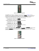
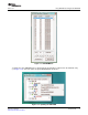
Figure 1-4. GPIO Control Register
• General control register (PCI register offset: D4h in each downstream bridge)
– RCVR_PRSNT_EN = 0b – PRSNT pin is used to determine whether slot is present
– REFCK_DIS = 0b – REFCK enabled
– LINK_ACT_RPT_CAP = 1b – Slot is link active reporting capable
– SLOT_PRSNT = 1b – Port connected to slot
• General slot info register (PCI register offset EEh in each downstream bridge)
– SLOT_NUM = 1b for slot 1, 2b for slot 2, and 3b for slot 3
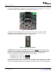
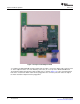
In hot-plug mode, the EVM board utilizes the TPS2363 PCIe server dual-slot hot-plug controller to switch
power on and off to slots 1 and 2. The TPS2363 is directly controlled by the hot-plug controller built into
the XIO3130. Slot 3 operates in normal mode. To configure the EVM for hot-plug operation, the six
jumpers (J7, J11, J13, J14, J15, J16) must be removed (see Figure 1-5 ).
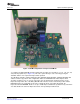
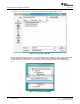
Figure 1-5. Power Jumpers
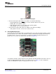
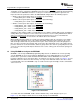
The dipswitch should be configured with SCL, DN1_DPSTRP and DN2_DPSTRP slide switches in the up
position, and DN3_DPSTRP slide switches in the down position (see Figure 1-6 ). This configuration
enables the EEPROM and enables hot-plug operation on slots 1 and 2.
SLLU108 – July 2008 XIO3130 EVM 3
Submit Documentation Feedback