
User's Manual
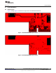
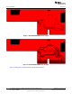


Table Of Contents

www.ti.com
Layout Guidelines
Figure 11. Module Layout Guidelines (Top Layer)
Figure 12. Module Layout Guidelines (Bottom Layer)
Table 3 describes the guidelines corresponding to the reference numbers in Figure 11 and Figure 12.
Table 3. Module Layout Guidelines
Reference Guideline Description
1 Keep the proximity of ground vias close to the pad.
2 Do not run signal traces underneath the module on the layer where the module is mounted.
3 Have a complete ground pour in layer 2 for thermal dissipation.
4 Ensure a solid ground plane and ground vias under the module for stable system and thermal dissipation.
5 Increase ground pour in the first layer and have all traces from the first layer on the inner layers, if possible.
6 Signal traces can be run on a third layer under the solid ground layer and the module mounting layer.
13
SWRU382–November 2014 WL1837MODCOM8I WLAN MIMO and Bluetooth
®
Module Evaluation Board for
TI Sitara™ Platform
Submit Documentation Feedback
Copyright © 2014, Texas Instruments Incorporated