
User Guide
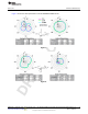
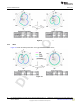
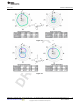

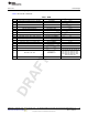
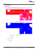
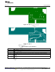
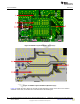
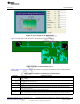
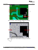
Table Of Contents

www.ti.com
Layout Guidelines
Figure 16. Layer 3
Figure 17. Layer 4
Table 2. Module Layout Guidelines
Reference Guideline Description
1 The proximity of ground vias must be close to the pad.
2 Signal traces must not be run underneath the module on the layer where the module is mounted.
3 Have a complete ground pour in layer 2 for thermal dissipation.
4 Have a solid ground plane and ground vias under the module for stable system and thermal dissipation.
Increase the ground pour in the first layer and have all of the traces from the first layer on the inner layers, if
5
possible.
Signal traces can be run on a third layer under the solid ground layer, which is below the module mounting
6
layer.
17
SWRU359A–September 2013–Revised October 2013 WL1835MODCOM8A WLAN MIMO and BT Module Evaluation Board for TI
Sitara™ Platform
Submit Documentation Feedback
Copyright © 2013, Texas Instruments Incorporated