
- Texas Instraments 48-V to 3.3-V Forward Converter with Active Clamp Reset Model SLUU178A User's Guide


www.ti.com
8 EVM Assembly Drawing and Layout
EVM Assembly Drawing and Layout
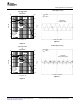
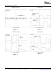
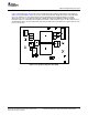
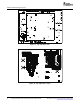
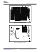
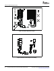
Figure 14 through Figure 20 show the top-side and bottom-side component placement for the EVM, as
well as device pin numbers where necessary. A four layer PCB was designed using the top and bottom
layers for signal traces and component placement along with an internal ground plane. The PCB
dimensions are 3.6" x 2.7" with a design goal of fitting all components within the industry standard
half-brick format, as outlined by the box dimensions 2.28" x 2.20" shown in Figure 15 . All components are
standard OTS surface mount components placed on the both sides of the PCB. The copper-etch for each
layer is also shown.
Figure 14. Top Side Component Assembly
SLUU178A – November 2003 – Revised December 2006 Using the UCC2891 Active Clamp Current Mode PWM Controller 13
Submit Documentation Feedback