
Datasheet


TVP7002
www.ti.com
SLES206C –MAY 2007–REVISED APRIL 2013
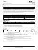
Fine Clamp Control
Subaddress 2Ah Default (07h)
7 6 5 4 3 2 1 0
CM Offset Reserved Fine swsel [1:0] Reserved Fine GB Fine R
CM Offset: Fine bottom-level clamp common mode offset enable. The common mode offset is approximately 300 mV when enabled. Has
no effect when the coarse clamp or fine mid-level clamp is selected. See registers 10h and 2Dh.
0 = Common mode offset disabled (default)
1 = Common mode offset enabled
NOTE: The 300-mV common-mode offset can be enabled to improve isolation and channel crosstalk, when inputs with
sync tips larger than nominal (>300 mV) must be supported.
Reserved [6:5]:
0 = Normal operation (default)
Fine swse [1:0]l: Fine clamp time constant adjustment
00 = Longest time constant (default)
11 = Shortest time constant
Reserved [2]:
1 = Normal operation (default)
Fine GB: Active-high fine clamp enable for Green and Blue channel
0 = Green channel fine clamp disabled
1 = Green and Blue channel fine clamps enabled (default)
Fine R: Active-high fine clamp enable for Red channel
0 = Red channel fine clamp disabled
1 = Red channel fine clamp enabled (default)
NOTE: Leave Fine GB and Fine R bits turned on for proper clamp operation. See register 10h for mid and bottom level clamping control.
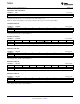
Power Control
Subaddress 2Bh (Default 00h)
7 6 5 4 3 2 1 0
Reserved SOG SLICER REF CURRENT PW ADC B PW ADC G PW ADC R
SOG:
0 = Normal operation (default)
1 = SOG power-down
Slicer:
0 = Normal operation (default)
1 = Slicer power-down
Reference:
0 = Normal operation (default)
1 = Reference block power-down
Current control:
0 = Normal operation (default)
1 = Current control block power-down
PW ADC B: Active-high power-down for ADC Blue channel
0 = ADC Blue channel power-down disabled (default)
1 = ADC Blue channel power-down enabled
PW ADC G: Active-high power-down for ADC Green channel
0 = ADC Green channel power-down disabled (default)
1 = ADC Green channel power-down enabled
PW ADC R: Active-high power-down for ADC Red channel
0 = ADC Red channel power-down disabled (default)
1 = ADC Red channel power-down enabled
Copyright © 2007–2013, Texas Instruments Incorporated Submit Documentation Feedback 43
Product Folder Links: TVP7002