
Datasheet


TUSB7320, TUSB7340
www.ti.com
SLLSE76E–MARCH 2011– REVISED JULY 2011
When enabled, the receiver equalization logic analyzes data patterns and transition times to determine
whether the low frequency gain of the equalizer should be increased or decreased. For the fully adaptive
setting (EQ = 0001), if the low frequency gain reaches the minimum value, the zero frequency is then
reduced. Likewise, if it reaches the maximum value, the zero frequency is then increased.
The decision logic is implemented as a voting algorithm with a relatively long analysis interval. The slow
time constant that results reduces the probability of incorrect decisions but allows the equalizer to
compensate for the relatively stable response of the channel.
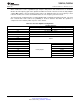
Table 8-3. Receiver Equalizer Configuration
Amplitude Reduction
EQ Value
Low Frequency Gain Zero Frequency
0000 Maximum -
0001 Fully Adaptive, FTC Normal
0010 Fully Adaptive, FTC Reversed
0011 Hold
0100
0101
Initialize
0110
0111
1000 365 MHz
1001 275 MHz
1010 195 MHz
1011 140 MHz
Partially Adaptive
1100 105 MHz
1101 75 MHz
1110 55 MHz
1111 50 MHz
Copyright © 2011, Texas Instruments Incorporated PHY CONTROL 101
Submit Documentation Feedback
Product Folder Link(s): TUSB7320 TUSB7340