
Datasheet


TUSB7320, TUSB7340
SLLSE76E–MARCH 2011– REVISED JULY 2011
www.ti.com
10 PCI EXPRESS POWER MANAGEMENT
10.1 Power Management
PCI power management (PM) features include active-state link PM, PME mechanisms, and all
conventional PCI D states. If the active-state link PM is enabled, the link automatically saves power when
idle using the L0s and L1 states.
10.2 PCI Express Link Power Management States
PCI Express defines Link power management states, replacing the bus power management states that
were defined by the PCI Bus Power Management Interface Specification. Link states are not visible to
PCI-PM legacy compatible software, and are either derived from the power management D-states of the
corresponding components connected to that Link or by ASPM protocols.
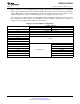
Table 10-1. PCI Express Link Power Management States
Link States Description
L0 Active state. All PCI Express transactions and other operations are enabled.
L0s A low resume latency, energy saving "standby" state.
L1 Higher latency, lower power "standby" state.
L2 Auxiliary-powered Link, deep-energy-saving state.
L3 Link Off state. When no power is present, the component is in the L3 state.
Link States Description PM SW Directed Ref Clk Vaux
L0 Fully active Yes (D0) On On/Off
L0s Standby No On On/Off
L1 Low power standby Yes (D1-D3hot) On On/Off
L2/L3 Ready Staging for power removal Yes On On/Off
L2 Low power sleep Yes Off On
L3 No power N/A Off Off
10.3 PCI Express Power Management D-States
PCI Express supports all PCI-PM device power management states. The TUSB73x0 supports the D0, D1,
D2, and D3 states (both D3hot and D3cold).
Table 10-2. PCI Express Power Management D-States
Power Management States Description
Normal operation state. The device is completely active and responsive in this state. The
D0
link may be L0 or L0s.
Light sleep state. I Configuration and message requests are accepted. Intermediate
D1 state intended to provide some power savings but yields a quicker restore time. The link
state is L1.
Deep sleep state. Configuration and message requests are accepted. Intermediate state
D2 intended to provide some power savings but yields a quicker restore time. The link state
is L1.
Disabled State. Configuration and message requests are accepted. Link state should be
D3hot
L1, PERST# is deasserted, and reference clock active depending on state of CLKREQ#.
Power-off state. Link state should be L2. PERST# is active and no reference clock is
D3cold
present.
104 PCI EXPRESS POWER MANAGEMENT Copyright © 2011, Texas Instruments Incorporated
Submit Documentation Feedback
Product Folder Link(s): TUSB7320 TUSB7340