
Marine Radio - Marine Radio Decoder User Manual

8.4.2 Input Sign
8.4.3 Log Equation
8.4.4 Re-Encode
9 Programming
Programming
www.ti.com
The TCP assumes that the encoded bits are converted into signed binary symbols using the following
mapping: 0 → -1, 1 → +1 and scaled by -2*a/ Σ
2
where a is the fading factor and Σ is the noise variance.
Many receivers may perform this scaling without applying the -1 factor. With TCP, this requires the DSP to
perform the -1 multiplication as the TCP expects this scaling. In TCP2, the -1 multiplication can be
performed automatically by the TCP2 based on the INPUTSIGN bit field of the TCPIC3 configuration
register. This reduces DSP overhead and does not cost extra TCP2 cycles.
The exact mathematical equation for forward and backward recursion in a MAP decoder is based on a log
of a sum of two exponential terms, In(e
A
+ e
B
). Due to the complexity of hardware implementation, this
expression is often approximated with the co-called max* term, which is computed as max* (A, B) = max
(A, B) + In(l + e |-
A-B
|)); i.e., the maximum of the exponents and a correction term which is a function of the
difference of the exponents. The correction term is often implemented as a table look-up. Such decoder is
called Max* Log-MAP. If the correction term is dropped, the implementation becomes max-log-MAP.
While TCP uses a Max*-log-MAP implementation, TCP2 offers both Max* Log-MAP and max-log-MAP
implementations. This can be selected on a frame-by-frame basis. The second implementation does not
require the input LLRs (log-likelihood ratios) to be scaled by a factor inversely proportional to noise
variance, and is therefore more robust in situations where SNR can not be accurately estimated.
The re-encode block is directly connected to the CRC block. During the sub-block execution, up to 256
sets of data will be stored in a double buffered memory. Two bits each will be stored for x0, p0, and p1.
One bit is the sign bit and the other bit is set if the symbol is equal to a zero. These 6 bits will be used for
re-encoding. The seventh bit will be the hard decision bit. This bit is the sign of the following summation:
(x+a+w).
The decision bits can be re-encoded with a convolutional encoder. The output of the encoder is 3 bit
streams: systematic bit and 2 parity bits. These bits can be compared with the signs of the stored
systematic and parity symbols. If the bits match, then no error has occurred. If the bits do not match, then
an error has occurred. If the stored symbol is a zero, then no information can be determined from this
data. A zero symbol represents either a depunctured symbol or a symbol that is equal distance from the
ideal modulated +1 or -1. As the signs are compared, a running count of the total number of sign
differences is calculated. These counts can be used as an estimate of the channel quality.
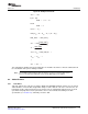
The cnt_re_map0 output register is a sum of the number of sign differences for MAP0. The cnt_re_map1
output register is a sum of the number of sign differences for MAP1. Table 41 shows the valid symbols
that can be used during the calculation of errors for each MAP.
Table 41. Valid Re-Encode Symbols Used for Comparison
MAP Valid Systematic (x) Valid Parity (p0) Valid Parity (p1)
0 Yes Yes Yes
1 No Yes Yes
The TCP2 requires setting up the following context per user channel:
• Standalone (SA) mode
– 3 to 5 EDMA3 parameters (see Table 42 )
– The input configurations parameters
• Shared-processing (SP) mode
– 3 to 4 EDMA3 parameters (see Table 43 )
– The input configurations parameters
64 TMS320C6457 Turbo-Decoder Coprocessor 2 SPRUGK1 – March 2009
Submit Documentation Feedback