
Marine Radio - Marine Radio Decoder User Manual

6.18 TCP2 Input Configuration Register 15 (TCPIC15)
www.ti.com
Registers
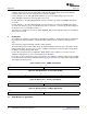
The TCP2 input configuration register 15 (TCPIC15) is shown in Figure 48 and described in Table 22 .
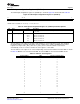
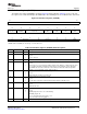
Figure 48. TCP2 Input Configuration Register 15 (TCPIC15)
31 24 23 0
Reserved EXT_SCALE_12_15
R/W-0 R/W-0
LEGEND: R/W = Read/Write; R = Read only; - n = value after reset
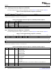
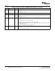
Table 22. TCP2 Input Configuration Register 15 (TCPIC15) Field Descriptions
Bit Field Value Description
31-24 Reserved 0 Reserved. The reserved bit location is always read as 0. A value written to this field
has no effect.
23-0 EXT_SCALE_12_15 0-FFFF FFFFh Extrinsic scale factor
23:18 Extrinsic scale factor 15
17:12 Extrinsic scale factor 14
11:6 Extrinsic scale factor 13
5:0 Extrinsic scale factor 12
The 16 extrinsic scale registers are 6 bits each and have a (1,5) fixed-point precision. The unsigned
fixed-point numbers can range from 0.0 to 1.0. For example, 0.5 is equal to 0.10000 or 0x10. These
registers are only used if e_max_star is 0. If e_max_star is 1, then the extrinsic scale factor is
automatically set to a 1.0. The reset value for each register is 1.0 or 0x20.
The 16 extrinsic scale registers are selected depending on the iteration number and active MAP as shown
in Table 23 . MAP 0 is the non-interleaved MAP decode and MAP1 is the interleaved MAP decode.
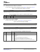
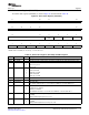
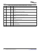
Table 23. Extrinsic Scale Registers
Iteration Number MAP Extrinsic Scaling Register
0 0 0
0 1 1
1 0 2
1 1 3
2 0 4
2 1 5
3 0 6
3 1 7
4 0 8
4 1 9
5 0 10
5 1 11
6 0 12
6 1 13
7 0 14
7 1 15
8 0 15
8 1 15
. . .
. . .
. . .
31 1 15
SPRUGK1 – March 2009 TMS320C6457 Turbo-Decoder Coprocessor 2 41
Submit Documentation Feedback