
Marine Radio - Marine Radio Decoder User Manual

www.ti.com
Shared-Processing (SP) Mode
Each sub-frame is independent of each other. There are three types of sub-frames. The first sub-frame
starts the trellis from the zero state. The last sub-frame ends the trellis from a known state. The remaining
middle subframes do not start or end from a known state.
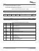
The EDMA3 transfers ACNT*BCNT number of bytes in A-Sync Mode and ACNT*BCNT*CCNT number of
bytes in AB-Sync Mode. The total number of bytes for both modes should be a multiple of 8. Also, the
starting address of the first sub-frame that the EDMA3 will transfer needs to be memory-mapped.
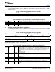
In the shared processing mode:
• Prolog length must be multiples of 8
• Starting address for reading extrinsic RAM must be:
RAM base address + middle and last subframes prolog length
• CRC is turned off
• SNR is turned off
• Prolog reduction is turned off
• Extrinsic scaling is turned off
The turbo decoding of the full frame is performed in several steps as described below:
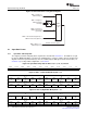
• The EDMA3 sends the input buffers for one sub-frame (the MAP0 inputs are described in Figure 19 ).
• The TCP2 performs the MAP0 for the current sub-frame.
• The EDMA3 reads the MAP output (extrinsic) of the current sub-frame and writes it into the DSP
memory.
The steps for the MAP0 process are repeated for all the other sub-frames.
Once all the sub-frames MAP0 have been computed, the full MAP0 extrinsic (= apriori 1) is then available.
This allows the DSP to interleave the extrinsic output 1 to prepare the next MAP (= MAP1). Once this
interleaving is done, the same process is applied, in MAP1 configuration:
• The EDMA3 sends the input buffers for one sub-frame (the MAP0 inputs are described in Figure 19 ).
• The TCP2 performs the MAP1 for the current sub-frame
• The EDMA3 reads the MAP output (extrinsic) of the current sub-frame and writes it into the DSP
memory.
The steps for the MAP1 process are repeated for all the other sub-frames.
Once all the sub-frames MAP1 have been computed, the full extrinsic (=apriori 2) is then available. This
allows the DSP to de-interleave the extrinsic output 2 to prepare the next MAP (=MAP0). Once this
de-interleaving is done, the same process is applied, in MAP0 configuration. Steps 1-4 are then repeated
for all iterations. The DSP is in charge of any stopping criteria algorithm implementation and computing
the final hard decisions. Figure 19 shows a description of the TCP2 processing unit functional block
diagram in shared processing mode.
SPRUGK1 – March 2009 TMS320C6457 Turbo-Decoder Coprocessor 2 21
Submit Documentation Feedback