
Datasheet


"#$%&'
SBAS417B − JUNE 2007 − REVISED JANUARY 2008
www.ti.com
14
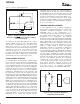
PRESSURE MEASUREMENT
Measuring touch pressure can also be done with the
TSC2046E. To determine pen or finger touch, the pressure
of the touch needs to be determined. Generally, it is not
necessary to have very high performance for this test;
therefore, the 8-bit resolution mode is recommended
(however, calculations shown here are in the 12-bit
resolution mode). There are several different ways of
performing this measurement. The TSC2046E supports
two methods. The first method requires knowing the
X-plate resistance, measurement of the X-Position, and
two additional cross panel measurements (Z
1
and Z
2
) of
the touch screen, as shown in Figure 8. Using Equation (3)
calculates the touch resistance:
R
TOUCH
+ R
X−Plate
@
X−Position
4096
ǒ
Z
2
Z
1
*1
Ǔ
The second method requires knowing both the X-plate
and Y-plate resistance, measurement of X-Position and
Y-Position, and Z
1
. Using Equation (4) also calculates
the touch resistance:
R
TOUCH
+
R
X−Plate
@ X−Position
4096
ǒ
4096
Z
1
*1
Ǔ
*R
Y−Plate
ǒ
1*
Y−Position
4096
Ǔ
DIGITAL INTERFACE
See Figure 9 for the typical operation of the TSC2046E
digital interface. This diagram assumes that the source of
the digital signals is a microcontroller or digital signal
processor with a basic serial interface. Each
communication between the processor and the converter,
such as SPI, SSI, or Microwiret synchronous serial
interface, consists of eight clock cycles. One complete
conversion can be accomplished with three serial
communications for a total of 24 clock cycles on the DCLK
input.
The first eight clock cycles are used to provide the control
byte via the DIN pin. When the converter has enough
information about the following conversion to set the input
multiplexer and reference inputs appropriately, the
converter enters the acquisition (sample) mode and, if
needed, the touch panel drivers are turned on. After three
more clock cycles, the control byte is complete and the
converter enters the conversion mode. At this point, the
input sample-and-hold goes into the hold mode and the
touch panel drivers turn off (in single-ended mode). The
next 12 clock cycles accomplish the actual analog-
to-digital conversion. If the conversion is ratiometric
(SER/DFR
= 0), the drivers are on during the conversion
and a 13th clock cycle is needed for the last bit of the
conversion result. Three more clock cycles are needed to
complete the last byte (DOUT will be low), which are
ignored by the converter.
X−Position
Measure
X−Position
Touch
X+ Y+
X
− Y
−
Measure
Z
1
−P o s i t i o n
Z
1
−Position
Touch
X+
Y+
Y
−
X
−
Measure
Z
2
−P o s i t i o n
Z
2
−P o s i t i o n
Touch
X+
Y+
Y
−
X
−
Figure 8. Pressure Measurement Block Diagrams
(3)
(4)