
Datasheet


"#$%&'
SBAS417B − JUNE 2007 − REVISED JANUARY 2008
www.ti.com
13
The second mode of operation does not require a test
temperature calibration, but uses a two-measurement
method to eliminate the need for absolute temperature
calibration and for achieving 2°C accuracy. This mode
requires a second conversion with an address of A2 = 1,
A1 = 1, and A0 = 1, with a 91 times larger current. The voltage
difference between the first and second conversion using 91
times the bias current is represented by Equation (1):
DV +
kT
q
@ In(N)
where:
N is the current ratio = 91.
k = Boltzmann’s constant = 1.3807 × 10
−23
J/K
(joules/kelvins).
q = the electron charge = 1.6022 × 10
–19
C (coulombs).
T = the temperature in kelvins (K).
This method can provide improved absolute temperature
measurement, but at a lower resolution of 1.6°C/LSB. The
resulting equation that solves for T is:
T +
q @ DV
k @ In(N)
where:
∆V = V
BE
(TEMP1) – V
BE
(TEMP0) (in mV)
∴
T = 2.573 ⋅ ∆V (in K)
or T = 2.573 ⋅ ∆V – 273 (in °C)
NOTE: The bias current for each diode temperature
measurement is only on for three clock cycles (during the
acquisition mode) and, therefore, does not add any
noticeable increase in power, especially if the temperature
measurement only occurs occasionally.
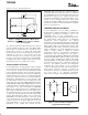
BATTERY MEASUREMENT
An added feature of the TSC2046E is the ability to monitor
the battery voltage on the other side of the voltage regulator
(dc/dc converter), as shown in Figure 7. The battery voltage
can vary from 0V to 6V, while maintaining the voltage to the
TSC2046E at 2.7V, 3.3V, etc. The input voltage (V
BAT
) is
divided down by four so that a 5.5V battery voltage is
represented as 1.375V to the ADC. This design simplifies the
multiplexer and control logic. In order to minimize the power
consumption, the divider is only on during the sampling
period when A2 = 0, A1 = 1, and A0 = 0 (see Table 1 for the
relationship between the control bits and configuration of the
TSC2046E).
+V
CC
V
BAT
7.5k
Ω
2.5k
Ω
DC/DC
Converter
Battery
0.5V
to
5.5V
0.125V to 1.375V
2.7V
+
ADC
Figure 7. Battery Measurement Functional Block
Diagram
(1)
(2)