
Evaluation Module User's Guide

www.ti.com
6 Kit Operation
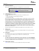
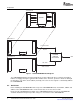
6.1 TSC2007EVM-PDK Block Diagram
Kit Operation
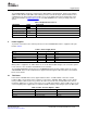
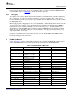
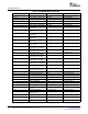
Table 6. List of Jumpers
JUMPER SHUNT POSITION JUMPER DESCRIPTION
JMP1 2-3 Analog power select (default is +3.3VD)
JMP2 Closed EEPROM address select. When installed and used with the USB-MODEVM, firmware for the
motherboard is executed from the EEPROM on the TSC2007EVM. This is the default mode.
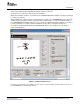
The following section provides information on using the TSC2007EVM-PDK, including setup, program
installation, and program usage.
A block diagram of the TSC2007EVM-PDK is shown in Figure 1 . The evaluation kit consists of two circuit
boards connected together. The motherboard is designated as the USB-MODEVM interface board; the
daughtercard is the TSC2007EVM described previously in this manual.
SLAU199 – March 2007 TSC2007EVM and TSC2007EVM-PDK User's Guide 5
Submit Documentation Feedback