
Host Controller Data Manual


4–38
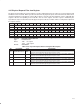
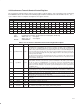
4.40 Isochronous Transmit Context Command Pointer Register
The isochronous transmit context command pointer register contains a pointer to the address of the first descriptor
block that the TSB12LV26 accesses when software enables an isochronous transmit context by setting the
isochronous transmit context control register (see Section 4.39) bit 15 (run). The n value in the following register
addresses indicates the context number (n = 0, 1, 2, 3, …, 7).
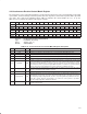
Bit 31 30 29 28 27 26 25 24 23 22 21 20 19 18 17 16
Name Isochronous transmit context command pointer
Type R R R R R R R R R R R R R R R R
Default X X X X X X X X X X X X X X X X
Bit 15 14 13 12 11 10 9 8 7 6 5 4 3 2 1 0
Name Isochronous transmit context command pointer
Type R R R R R R R R R R R R R R R R
Default X X X X X X X X X X X X X X X X
Register: Isochronous transmit context command pointer
Type: Read-only
Offset: 20Ch + (16 * n)
Default: XXXX XXXXh
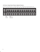
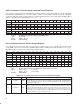
4.41 Isochronous Receive Context Control Register
The isochronous receive context control set/clear register controls options, state, and status for the isochronous
receive DMA contexts. The n value in the following register addresses indicates the context number (n = 0, 1, 2, 3).
See Table 4–30 for a complete description of the register contents.
Bit 31 30 29 28 27 26 25 24 23 22 21 20 19 18 17 16
Name Isochronous receive context control
Type RSC RSC RSCU RSC R R R R R R R R R R R R
Default X X X X 0 0 0 0 0 0 0 0 0 0 0 0
Bit 15 14 13 12 11 10 9 8 7 6 5 4 3 2 1 0
Name Isochronous receive context control
Type RSCU R R RSU RU RU R R RU RU RU RU RU RU RU RU
Default 0 0 0 X 0 0 0 0 X X X X X X X X
Register: Isochronous receive context control
Type: Read/Set/Clear/Update, Read/Set/Clear, Read/Update, Read-only
Offset: 400h + (32 * n) set register
404h + (32 * n) clear register
Default: X000 X0XXh
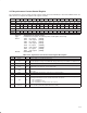
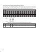
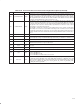
Table 4–30. Isochronous Receive Context Control Register Description
BIT FIELD NAME TYPE DESCRIPTION
31 bufferFill RSC
When this bit is set, received packets are placed back-to-back to completely fill each receive buffer.
When this bit is cleared, each received packet is placed in a single buffer. If bit 28 (multiChanMode)
is set to 1, then this bit must also be set to 1. The value of this bit must not be changed while bit 10
(active) or bit 15 (run) is set.
30 isochHeader RSC
When this bit is 1, received isochronous packets include the complete 4-byte isochronous packet
header seen by the link layer. The end of the packet is marked with xferStatus in the first doublet, and
a 16-bit timeStamp indicating the time of the most recently received (or sent) cycleStart packet.
When this bit is cleared, the packet header is stripped from received isochronous packets. The
packet header, if received, immediately precedes the packet payload. The value of this bit must not
be changed while bit 10 (active) or bit 15 (run) is set.