
Host Controller Data Manual


4–25
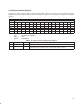
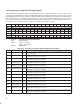
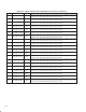
4.29 Node Identification Register
The node identification register contains the address of the node on which the OHCI-Lynx chip resides, and indicates
the valid node number status. The 16-bit combination of the busNumber field (bits 15–6) and the NodeNumber field
(bits 5–0) is referred to as the node ID. See Table 4–20 for a complete description of the register contents.
Bit 31 30 29 28 27 26 25 24 23 22 21 20 19 18 17 16
Name Node identification
Type RU RU R R RU R R R R R R R R R R R
Default 0 0 0 0 0 0 0 0 0 0 0 0 0 0 0 0
Bit 15 14 13 12 11 10 9 8 7 6 5 4 3 2 1 0
Name Node identification
Type RWU RWU RWU RWU RWU RWU RWU RWU RWU RWU RU RU RU RU RU RU
Default 1 1 1 1 1 1 1 1 1 1 X X X X X X
Register: Node identification
Type: Read/Write/Update, Read/Update, Read-only
Offset: E8h
Default: 0000 FFXXh
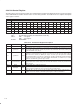
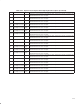
Table 4–20. Node Identification Register Description
BIT FIELD NAME TYPE DESCRIPTION
31 iDValid RU
This bit indicates whether or not the TSB12LV26 has a valid node number. It is cleared when a 1394 bus
reset is detected and set when the TSB12LV26 receives a new node number from the PHY.
30 root RU This bit is set during the bus reset process if the attached PHY is root.
29–28 RSVD R Reserved. Bits 29–28 return 0s when read.
27 CPS RU Set if the PHY is reporting that cable power status is OK.
26–16 RSVD R Reserved. Bits 26–16 return 0s when read.
15–6 BusNumber RWU
This number is used to identify the specific 1394 bus the TSB12LV26 belongs to when multiple
1394-compatible buses are connected via a bridge.
5–0 NodeNumber RU
This number is the physical node number established by the PHY during self-ID. It is automatically set
to the value received from the PHY after the self-ID phase. If the PHY sets the NodeNumber to 63, then
software should not set the run bit (bit 15) of the asynchronous context control register (see Section
4.37) for either of the AT DMA contexts.