
Datasheet
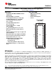


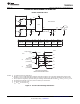


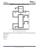
Table Of Contents
EXT TRIGGER
BIAS
Network Analyzer
(HP8753ES)
P1 P2
V
CC
A
X
B
X
SEL
DUT
V
BIAS
V
SEL
TS3DDR3812
www.ti.com
SCDS314A –FEBRUARY 2011– REVISED MARCH 2011
PARAMETER MEASUREMENT INFORMATION (continued)
Figure 7. Test Circuit for Frequency Response (BW)
Frequency response is measured at the output of the ON channel. For example, when V
SEL
= 0 and A
0
is the
input, the output is measured at B0. All unused analog I/O ports are left open.
HP8753ES Setup
Average = 4
RBW = 3 kHz
V
BIAS
= 0.35 V
ST = 2 s
P1 = 0 dBM
Copyright © 2011, Texas Instruments Incorporated Submit Documentation Feedback 9
Product Folder Link(s) :TS3DDR3812