
Datasheet
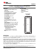


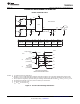


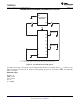
Table Of Contents
V
SEL
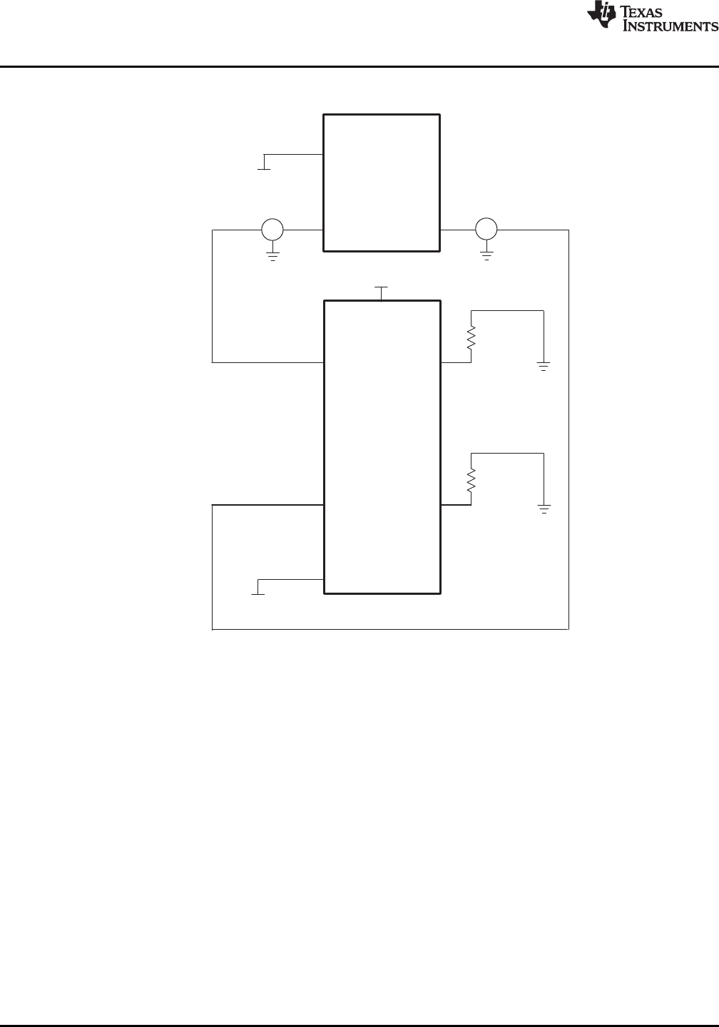
A. C includes probe and jig capacitance.
B. A 50 W termination resistor is needed to match the loading of the network analyzer.
L
V
BIAS
EXT TRIGGER
BIAS
Network Analyzer
(HP8753ES)
P1 P2
A
0
A
1
A
2
A
3
SEL
B
X
B
X
B
X
B
X
B
X
B
X
B
X
B
X
V
CC
R = 50
L
W
R = 50
L
W
TS3DDR3812
SCDS314A –FEBRUARY 2011– REVISED MARCH 2011
www.ti.com
PARAMETER MEASUREMENT INFORMATION (continued)
Figure 8. Test Circuit for Crosstalk (X
TALK
)
Crosstalk is measured at the output of the nonadjacent ON channel. For example, when V
SEL
= 0 and A
1
is the
input, the output is measured at A
3
. All unused analog input (A) ports are connected to GND, and output (B)
ports are left open.
HP8753ES Setup
Average = 4
RBW = 3 kHz
V
BIAS
= 0.35 V
ST = 2 s
P1 = 0 dBM
10 Submit Documentation Feedback Copyright © 2011, Texas Instruments Incorporated
Product Folder Link(s) :TS3DDR3812