
User manual


www.ti.com
TPS92310 Evaluation Board Test Procedure
7 TPS92310 Evaluation Board Test Procedure
CAUTION
High voltage levels are present on the evaluation module whenever it is
energized. Proper precautions must be taken when working with the EVM.
Serious injury can occur if proper safety precautions are not followed.
Table 3. Connections
Step Operation Remarks
1 Confirm the demo boards version. Check the demo board.
(120V
AC
TPS92310 120V EVM or
230V
AC
TPS92310 230V EVM)
2 Connect the AC source to AC line AC source voltage is 230V
AC
TPS92310 230V EVM
/120V
AC
TPS92310 120V EVM
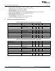
3 Connect the LED light or electronic load to If use electronic load, set the electronic load is 20V
connecter LED+ and LED-. (Figure 3) with CV mode. And make sure the LED + connect
to electronic load + and LED- connection electronic
load GND.
Table 4. Functional AC Input Test
Step Operation Remarks
4 Switch the power switch on the setup to ON Please confirm the AC1 and AC2 connection are
position. correct.
5 The LEDs lights up within 2 sec. Measure the The LED voltage is 21V. I
LED
current is 350mA +/-
convertor output voltage. 5% (electronic load loading value). If the V
LED
start
up <2 sec, Power Factor >0.9 and I
LED
between
330mA to 370mA
6 Switch off the power source. Don’t touching any connection within 2 sec after
power off.
5
SNVA631A–February 2012–Revised May 2013 AN-2214 TPS92310 Evaluation Module
Submit Documentation Feedback
Copyright © 2012–2013, Texas Instruments Incorporated