
User manual

I
EXAS
T
NSTRUMENTS
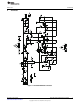
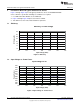
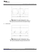
AMP Meter 1
AMP Meter 2
L.E.D Load
Volt Meter 1 Volt Meter 2
+ -
+ -
Dimmer
MaxMin
AC Source
7.10 7.2
Test Setup
www.ti.com
5 Test Setup
WARNING
High voltages that may cause injury exist on this evaluation
module (EVM). Please ensure all safety procedures are followed
when working on this EVM. Never leave a powered EVM
unattended. The use of isolated equipment is highly recommended.
5.1 Test Equipment
Voltage Source: 105 V
RMS
to 135 V
RMS
isolated AC source capable of at least 20 W.
Multimeters: Two voltmeters for measuring up to 35 V
DC
each and two ammeters for up to 1 A each.
Output Load: 9 LEDs in series (VF = 3.4 V at 330 mA per LED)
Oscilloscope: 4 channel 100 MHz with high-voltage probe rated for at least 600 V.
Recommended Wire Gauge: 18 AWG not more than two feet long.
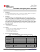
5.2 TPS92001EVM-645 Recommended Test Setup
Figure 2. Recommended Test Set Up
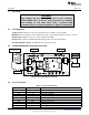
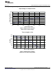
5.3 List of Test Points
Table 2. Test Point Functions
TEST POINTS NAME DESCRIPTION
TP1 LED + LED output
TP2 LED ¬- LED return point
TP3 CS Feedback pin of TPS92001
TP4 CT Clock signal
TP5 SW Buck switch node
TP6 Bulk- Rectified AC negative input
TP7 Bulk + Rectified AC positive input
TP8 Line AC line input
TP9 Neutral AC neutral input
4
Dimmable LED Lighting Driver Controller SLUU897– March 2012
Submit Documentation Feedback
Copyright © 2012, Texas Instruments Incorporated